Boost Switching
Found 8 free book(s)
400KHz 60V 2A Switching Current Boost / Buck-Boost ...
www.xlsemi.com400KHz 60V 2A Switching Current Boost / Buck-Boost / Inverting DC/DC Converter Rev 1.2 www.xlsemi.com 2 Pin Configurations XL6007 1 3 5 2 4SW EN FB VIN NC 6 7 8 SW GND GND Figure2. Pin Configuration of XL6007 (Top View) Table 1 Pin Description Pin Number Pin Name Description 1 EN

DESIGN OF SINGLE PHASE BOOST POWER FACTOR …
web.wpi.eduboost power factor correction circuit and design of its control system. 1.2 Disadvantage due to Harmonic Current in Power Grid [2] In fact, the decrease of power factor caused by harmonic current already exists for a long time. People don’t pay much attention because the use of switching devices is not

Buck-Boost DC-DC Converter 25A / 50A / 100A
www.victronenergy.comrelated programmable time-delayed switching. This also prevents the onboard voltage of the vehicle from becoming too low. It is not necessary to intervene in the system of the vehicle, install a separate motor run sensor or intervene in the CAN bus system. Apart from this detection, the Buck-Boost series equipment can also be switched on with a
Number of parameters (M)
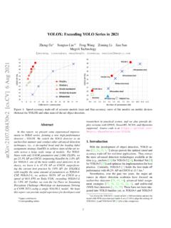
arxiv.orgthe above techniques, we boost the YOLOv3 to 47.3% AP (YOLOX-DarkNet53) on COCO with 640 ture of DarkNet53 backbone and an SPP layer, referred640 res-olution, surpassing the current best practice of YOLOv3 (44.3% AP, ultralytics version2) by a large margin. More-over, when switching to the advanced YOLOv5 architec-
Switching regulator fundamentals (Rev. C)
www.ti.comThis paper will detail the operating principles of the four most commonly used switching converter types: Buck— used to reduce a DC voltage to a lower DC voltage. Boost— provides an output voltage that is higher than the input. Buck-Boost (invert)—an output voltage that is generated opposite in polarity to the input.
LTC3780 (Rev G) - Analog Devices
www.analog.com4-Switch Buck-Boost Controller The LTC®3780 is a high performance buck-boost switch - ing regulator controller that operates from input voltages above, below or equal to the output voltage. The constant frequency current mode architecture allows a phase-lockable frequency of up to 400kHz. With a wide 4V to
TOP VIEW - Diodes Incorporated
www.diodes.comHigh-Side Gate Drive Boost Input. BST supplies the drive for the high-side N-Channel power MOSFET. A 100nF capacitor is recommended from BST to SW to power the high-side driver. VIN 2 Power Input. VIN supplies the power to the IC as well as the step-down converter power MOSFETs. Drive VIN with a 3.8V to 40V power source.
10th Generation Intel Core™ Processor Families
www.intel.comDocument Number: 341077-005 10th Generation Intel® Core™ Processor Families Datasheet, Volume 1 of 2 Supporting 10th Generation Intel® Core™ Processor Families, Intel® Pentium® Processors, Intel® Celeron® Processors for U/Y Platforms, formerly known as Ice Lake July 2020