Chapter 12 abutments
Found 12 free book(s)
WisDOT Bridge Manual Chapter 36 – Box Culverts
wisconsindot.govChapter 36 – Box Culverts July 2021 36-7 Bridges Advantages Disadvantages Less susceptible to clogging with drift, ice and debris Require more structural maintenance than culverts Waterway width increases with rising water surface until water begins to submerge structure Piers and abutments susceptible to scour failure
WisDOT Bridge Manual Chapter 24 – Steel Girder Structures
wisconsindot.govWhen one abutment has fixed bearings, see Chapter 12 – Abutments for the limitation on the length of a continuous segment. 24.1.3 Fundamental Concepts of Steel I-Girders . This section describes basic concepts of I-girder sections to aid in understanding the design

Straumann® Novaloc® Retentive System for Hybrid …
www.straumann.comCoping (see chapter 3 Using the Novaloc® Tools). For straight abutments use the straight, for angled abutments the angled analog. Step 2 – Fabricating the master cast. ѹ. Pour a master model using standard methods and type-4 dental stone (DIN 6873). Note: The master model can also be created with an implant-level im-pression. 1. 1. 2. 2
Chapter 12 Abutments - Wisconsin Department of …
wisconsindot.govChapter 12 – Abutments July 2021 12-7 . Figure 12.2-3 Sill Abutment Sill abutments are the least expensive abutment type and are usually the easiest to construct. However, this abutment type results in a higher superstructure cost, so the overall cost of the structure should be evaluated with other alternatives.
Bridge Design Manual - LRFD (LRF)
onlinemanuals.txdot.govChapter 4, Substructure Design. Policy on LRFD design of specific bridge substructure components. Chapter 5, Other Designs. Design guidelines for bridge widenings, steel-reinforced elastomeric bearings fo r pretensioned concrete beams, stru t-and-tie method, and culverts. This chapter also addresses corrosion protection measures.
CHAPTER 8 DRAINAGE AND DRAINAGE SYSTEMS
www.dot.state.pa.usU/ "3 10-12 CHAPTER 8 DRAINAGE AND DRAINAGE SYSTEMS ... directed toward bridge abutments. All surface water should eventually lead to the groundwater and/or a natural watercourse. In order to accomplish this, manmade watercourses are …
Design Standards No. 13 Embankment Dams
www.usbr.govfloating debris. This chapter presents guidelines for site-specific design of riprap slope protection (figure 7.1.1-1) subject to wave action. The primary focus is the prevention of riprap rock displacement and bedding erosion by wave action. This chapter also presents a discussion of other major considerations and procedures
Chapter 7 Substructure Design Contents
www.wsdot.wa.gov• At abutments – Approximate maximum top of foundation elevation. • At interior piers – The initial size, shape and number of columns and how they are configured with the foundation (e.g., whether a single foundation element supports each column, or one foundation element supports multiple columns)
Seattle SDCI – Seattle Building Code, Chapter 6, Types of ...
www.seattle.gov32 inch (12 mm) thick; 2. Gypsum board not less than 1/ 2 inch (12.7 mm) thick; or 3. A noncombustible material. TABLE 602.4 WOOD MEMBER SIZE EQUIVALENCIES For SI: 1 inch = 25.4 mm. 602.4.3 Columns. Wood columns shall be sawn or glued laminated and shall be not less than 8 inches (203 mm), nominal, in any dimension where supporting floor loads
Virginia Department of Transportation
www.virginiadot.orgGRIT Manual – Chapter 1 Page 1-2 We Keep Virginia Moving! Table 1: FIRST HARMFUL EVENT FIXED-OBJECT FATALITIES (Virginia 2011-2015) BY OBJECT TYPE
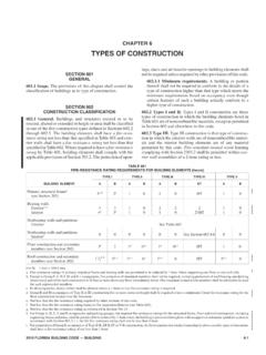
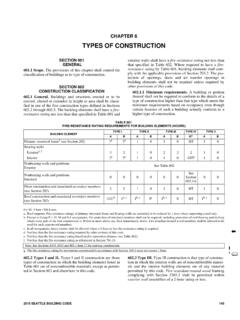
CHAPTER 6 TYPES OF CONSTRUCTION
www.ecodes.biz(12 mm) wood structural panel or 0.5-inch (12.7 mm) particleboard. The lumber shall be laid so that no continu-ous line of joints will occur except at points of support. Floors shall not extend closer than 0.5 inch (12.7 mm) to walls. Such 0.5-inch (12.7 mm) space shall be covered by a molding fastened to the wall and so arranged that it will not
Fixed Prosthodontics – Dental Coverage Guideline
www.uhcprovider.comRepairs or adjustments performed more than 12 months after the initial insertion; limited to 1 per consecutive 6 months Subject to a 12 month Waiting Period Replacement of fixed prosthesis, if damage or breakage was directly related to provider error: This type of replacement is the responsibility of the Dentist.