Chapter 2 design for shear engineering
Found 10 free book(s)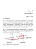
Chapter 2 Design for Shear - Engineering
by.genie.uottawa.caChapter 2 Design for Shear By Richard W. Furlong 2.1 Introduction Shear is the term assigned to forces that act perpendicular to the longitudinal axis of structural elements.

5.1 Seismic Design Categories - c.ymcdn.com
c.ymcdn.comCHAPTER 5. 57. EARTHQUAKE-RESISTANT DESIGN CONCEPTS. Chapter 5 DESIGN REQUIREMENTS. 5.1 Seismic Design Categories. The NEHRP Recommended Seismic Provisions
Chapter 5 Footing Design - Engineering
by.genie.uottawa.ca1 Chapter 5 Footing Design By S. Ali Mirza1 and William Brant2 5.1 Introduction Reinforced concrete foundations, or footings, transmit loads from a …

CHAPTER 2 PAVEMENT COMPOSITION AND …
www.nra.co.zaSouth African Pavement Engineering Manual Chapter 2: Pavement Composition and Behaviour Preliminary Section Page iii Chapter 11: Documentation and Tendering covers the different forms of contracts typical for road pavement projects; the design, contract and tender documentation; and, the tender process.

PRESTRESSED CONCRETE ANALYSIS AND DESIGN: …
technopress3000.comPRESTRESSED CONCRETE ANALYSIS AND DESIGN: FUNDAMENTALS Second Edition, 2004 by Antoine E. Naaman, Ph.D. Fellow ACI; Fellow ASCE; Fellow PCI; Fellow IFS Professor of Civil Engineering, University of
Lecture Slides
web.itu.edu.trWelding Symbols Arrow side of a joint is the line, side, area, or near member to which the arrow points The side opposite the arrow side is the other side Shape of weld is shown with the symbols below Shigley’s Mechanical Engineering Design Fig. 9–2
Chapter 2 - Design Considerations
www.ngma.comNGMA Structural Design Manual Chapter 2 - 1 Chapter 2 - Design Considerations 2.0 General 2.0.1 Scope Greenhouse structures designed per this manual shall meet the requirements of the International

Chapter III - GEOTECHNICAL ENGINEERING
www.virginiadot.orgMay 2012 1 Chapter III - GEOTECHNICAL ENGINEERING . SECTION 301 INTRODUCTION . This Manual of Instructions (MOI) presents minimum requirements for conducting geotechnical
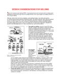
Chapter 14-DESIGN CONSIDERATIONS FOR WELDING
homepages.cae.wisc.eduWeld Joint Design Figure 3. Common weld joints for stampings and sheet metal fabrications. Several types of joints can be appropriate for welded sheet
CHAPTER 25 GYPSUM BOARD AND PLASTER - …
www2.iccsafe.orgCHAPTER 25 GYPSUM BOARD AND PLASTER TABLE 2503 (continued) MATERIALS SECTION 2504 APPLICATION 2504.1 Interior lathing and plastering 2504.1.1 Installation of interior gypsum lathing and fur
Similar queries
Chapter 2 Design for Shear - Engineering, Chapter 2 Design for Shear, Shear, 5.1 Seismic Design Categories, Chapter, Design, Chapter 5 Footing Design, Engineering, CHAPTER 2 PAVEMENT, Pavement Engineering, Chapter 2, Pavement, PRESTRESSED CONCRETE ANALYSIS AND DESIGN:, PRESTRESSED CONCRETE ANALYSIS AND DESIGN: FUNDAMENTALS, Lecture Slides, Engineering Design, Chapter 2 - Design Considerations, Chapter 2 - Design Considerations 2, GEOTECHNICAL ENGINEERING, CHAPTER 25 GYPSUM BOARD AND PLASTER