Common connection diagrams
Found 4 free book(s)
DRS/DRE/DRP/DRN Common Connection Diagrams
download.sew-eurodrive.com2018 Common Connection Diagrams 7 2.5 Wire and ring terminal specifications 2.5.1 BG or BGE When connecting the supply power from the motor terminal block to the brake rectifier, follow the specifications below. Connecting wire should be AWG14, MTW, 600V, 105°C temperature rating and black color.

Study Unit Understanding and Using Electronic Diagrams
www.workforcedevelopment.comto reading these, you’ll recognize common characteristics in all schematics. Schematic Diagrams Schematic diagrams document the connection points and construction methods of electrical and electronic circuits. Figure 1shows a simple schematic diagram of a power sup-ply; on it you can see some of the conventions used. Figure 2
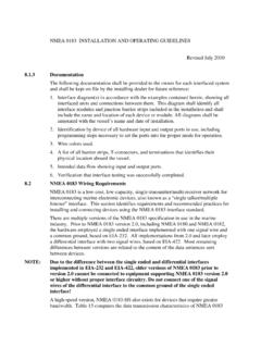
NMEA 0183 INSTALLATION AND OPERATING GUIDELINES
www.navcen.uscg.govAll diagrams shall be annotated with the vessel’s name and date of installation. ... to NMEA 0183 with the only difference being that a third connection “C” is available at each interface to ensure that the common mode ground potential is the same at all drivers and receivers.
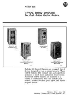
800-2.0 Typical Wiring Diagrams for Push Button Control ...
literature.rockwellautomation.comTypical Wiring Diagrams For PushButton Control Stations Start-Stop Control Wiring Diagrams SINGLE STATION -BASIC CIRCUIT r ----- 1 kla,I! I zl II I I II I I fo 0; 1 ----- J START 2 3 STOP I N.O. 1 Aux. I OPERATION-Depressing the START button energizes coil M, hold-in contacts M and maintains the circuit after the START button is released.