Example: bankruptcy
DRS/DRE/DRP/DRN Common Connection Diagrams
2018 Common Connection Diagrams 7 2.5 Wire and ring terminal specifications 2.5.1 BG or BGE When connecting the supply power from the motor terminal block to the brake rectifier, follow the specifications below. Connecting wire should be AWG14, MTW, 600V, 105°C temperature rating and black color.
Tags:
Information
Domain:
Source:
Link to this page:
Documents from same domain

2 Product Description - SEW Eurodrive
download.sew-eurodrive.comProduct Description 2 Product Description ... higher at time of delivery than after hours of regular ... Contact your sales representative to assist you in such cases.

MOVISAFE® UCS..B Compact Safety Modules
download.sew-eurodrive.comContents Operating Instructions – MOVISAFE3 ® UCS..B Compact Safety Modules Contents1General information.....

Information regarding UL - SEW Eurodrive
download.sew-eurodrive.comAntriebstechnik \ Antriebsautomatisierung \ Systemintegration \ Services*23056916_1216* Data sheet MOVITRACInformation regarding UL® 07B, MOVITRAC® 07A Ausgabe 12/2016 23056916/DE
MOVIDRIVE® MDX60A/61B/62B/MDR60A/61B, …
download.sew-eurodrive.comDrive Technologie \ Drive Automation \ System Integration \ Services Operating Instructions MOVIDRIVE® MDX60B/61B/62B, MOVIDRIVE® MDR60A/61B MOVIDRIVE® compact, MOVIDRIVE® A

12 W.. 1 2 3 4 5 W.7/AM.. 6 - SEW Eurodrive
download.sew-eurodrive.com– GK2010 515 12 1 2 3 4 5 6 7 8 9 10 11 12 13 14 15 16 17 18 19 20 21 22 W.. AM.. [Nm] W.. 12.1.1 W37 ne = 1400 1/min 110 Nm i na Ma max FRa ϕ (/R) AM [1/min] [Nm] [N] [ ' ] 63 71 80 90 W37 3.20 438 70 2220 -
MOVITRAC® B Information regarding UL / …
download.sew-eurodrive.comAntriebstechnik \ Antriebsautomatisierung \ Systemintegration \ Services Operating Instructions MOVITRAC® B Information regarding UL Edition 07/2012 20014546 / EN

SEW-EURODRIVE GmbH & Co KG – www.sew …
download.sew-eurodrive.comSEW-EURODRIVE GmbH & Co KG – www.sew-eurodrive.com 1 33 (1.3) 37.5 (1.48) 23 ±0.5 (0.91 ± 0.02) 26 (1.02) 202 (7.95) 130 (5.12) 12 (0.47) 24 (0.94)

EU Declaration of Conformity - download.sew-eurodrive.com
download.sew-eurodrive.comEU Declaration of Conformity Translation of the original textSEW-EURODRIVE GmbH & Co. KG 903280018/EN Ernst-Blickle-Straße 42, D-76646 Bruchsal declares under sole responsibility that the following products Bruchsal

Service - download.sew-eurodrive.com
download.sew-eurodrive.com3 6 Instruções de Operação – Motores CA DR/DZ/DX/DTE/DVE / Servomotores Assíncronos CT / CV Estrutura geral dos motores CA Estrutura do motor 3 Estrutura do motor 3.1 Estrutura geral dos motores CA A figura seguinte deve ser entendida como diagrama de bloco.

2 Product Description - SEW Eurodrive
download.sew-eurodrive.comCatalog – DRS-GM 06/2009 11 2 General notes on the product description Product Description 2 Coating Gear units, motors and gearmotors from SEW-EURODRIVE are painted with "blue/gray"/RAL 7031 machine paint according to DIN 1843 as standard.
Related documents

Study Unit Understanding and Using Electronic Diagrams
www.workforcedevelopment.comto reading these, you’ll recognize common characteristics in all schematics. Schematic Diagrams Schematic diagrams document the connection points and construction methods of electrical and electronic circuits. Figure 1shows a simple schematic diagram of a power sup-ply; on it you can see some of the conventions used. Figure 2
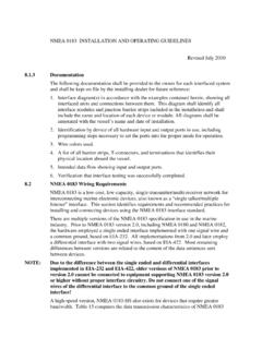
NMEA 0183 INSTALLATION AND OPERATING GUIDELINES
www.navcen.uscg.govAll diagrams shall be annotated with the vessel’s name and date of installation. ... to NMEA 0183 with the only difference being that a third connection “C” is available at each interface to ensure that the common mode ground potential is the same at all drivers and receivers.
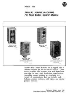
800-2.0 Typical Wiring Diagrams for Push Button Control ...
literature.rockwellautomation.comTypical Wiring Diagrams For PushButton Control Stations Start-Stop Control Wiring Diagrams SINGLE STATION -BASIC CIRCUIT r ----- 1 kla,I! I zl II I I II I I fo 0; 1 ----- J START 2 3 STOP I N.O. 1 Aux. I OPERATION-Depressing the START button energizes coil M, hold-in contacts M and maintains the circuit after the START button is released.