Compatible Eeprom
Found 7 free book(s)
GL850G Datasheet 108
www.kean.com.auEEPROM and then respond to the host the customized PID and VID configured in the external EEPROM. Default settings in the internal mask ROM is responded to the host without having external EEPROM. ... − Backward compatible to USB specification Revision 1.1

24AA512/24LC512/24FC512 512K I2C Serial EEPROM Data Sheet
ww1.microchip.comJan 05, 2010 · • 2-Wire Serial Interface, I2C™ Compatible • Cascadable for up to Eight Devices • Schmitt Trigger Inputs for Noise Suppression ... 512K I2C™ Serial EEPROM * 24XX512 is used in this document as a generic part number for the 24AA512/24LC512/24FC512 devices. 24AA512/24LC512/24FC512
Future Technology Devices International Ltd
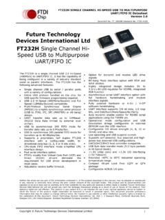
www.ftdichip.comEEPROM over the USB interface. Configurable I/O drives strength (4, 8, 12 or 16mA) and slew rate. Low operating and USB suspend current. Supports self -powered, bus powered and high power bus powered USB configurations. UHCI/OHCI/EHCI host controller compatible. USB Bulk data transfer mode (512 byte packets in Hi-Speed mode).

AT28C16 16K (2K x 8) Parallel EEPROMs
cva.stanford.edu• CMOS & TTL Compatible Inputs and Outputs • JEDEC Approved Byte Wide Pinout • Commercial and Industrial Temperature Ranges Description The AT28C16 is a low-power, high-performance Electrically Erasable and Program-mable Read Only Memory with easy to use features. The AT28C16 is a 16K memory organized as 2,048 words by 8 bits.
Future Technology Devices International Ltd
www.ftdichip.comEEPROM over the USB interface. Low operating and USB suspend current. Configurable I/O drive strength (4, 8, 12 or 16mA) and slew rate. Supports bus powered, self-powered and high - power bus powered USB configurations. UHCI/OHCI/EHCI host controller compatible. USB Bulk data transfer mode (512 byte packets

D2XX Programmer's Guide
www.ftdichip.comdevice into a different mode or writing data into the device EEPROM. In the case of the FTDI drivers for Windows, the D2XX driver and VCP driver are distributed in the same driver package, called the Combined Driver Model (CDM) package. Figure 2.1 Windows CDM Driver Architecture illustrates the architecture of the Windows CDM driver.

THE I2C-BUS SPECIFICATION VERSION 2.1 JANUARY 2000
i2c2p.twibright.comdownwards compatible i.e. they can be used in a 0 to 100 kbit/s I2C-bus system. •10-bit addressing is added. This allows 1024 additional slave addresses. •Slope control and input filtering for Fast-mode devices is specified to improve the EMC behaviour. NOTE: Neither the 100 kbit/s I2C-bus system nor the 100 kbit/s devices have been changed.