Determine The Voltage Divider And
Found 6 free book(s)
Bipolar Junction Transistors (BJT)
faculty.cord.eduVoltage-Divider Biasing • Likewise the emitter current can be found from • The collector current and DC collector voltage are . v out R 2 4.7 kΩ 2N3904 R 1 10 kΩ +V CC 15 V R E 2.7 kΩ R C 3.9 kΩ v in Q-Point • We still need to determine the optimal values for the DC biasing in order to choose resistors, etc.

Chapter 16 Oscillator Circuits and Applications
staff.utar.edu.mywhere A V is the voltage gain of the amplifier and β = V Vout f is the feedback ... Many oscillators are designed utilizing RC network and resistor divider circuits. RC network is basically used to determine the resonant frequency of the oscillator, whilst resistor divider circuit is used to provide attenuated feedback. ...
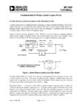
MT-086: Fundamentals of Phase Locked Loops (PLLs)
www.analog.comA phase-locked loop is a feedback system combining a voltage controlled oscillator (VCO) and a ... Divider set at 1000. Then, the N-value in the feedback would need to be of the order of 90,000. ... and the channel spacing determine the value of …

A Level Physics - Edexcel
qualifications.pearson.comThe peak voltage of the mains supply is given by A 230 2 V ... , determine the upward force exerted by the support at Y ... resistor R in a potential divider circuit as shown. The heater circuit is connected across R and will switch on when the potential difference
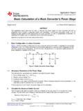
Basic Calculation of a Buck Converter's Power Stage (Rev. B)
www.ti.comWith the given feedback voltage, VFB, and feedback bias current, IFB, the voltage divider can be calculated. Figure 2. Resistive Divider for Setting the Output Voltage The current through the resistive divider needs to be at least 100 times as big as the feedback bias current: (9) IR1/2 = current through the resistive divider to GND

Chapter 2. - DC Biasing - BJTs
ajaybolar.weebly.comTwo methods of analyzing a voltage divider bias circuit are: Exact method – can be applied to any voltage divider circuit Approximate method – direct method, saves time and energy, can be applied in most of the circuits. Exact method In this method, the Thevenin equivalent network for the network to the left of the base terminal