Equivalent Circuit
Found 8 free book(s)
Audio Amplifier Circuit - UC Santa Barbara
web.ece.ucsb.edu1.2 Speaker Equivalent Circuit 9 1.3 Assemble Amplifier on Breadboard 9 1.4 Summing network 11 1.5 Optional -- Tone-Control Circuit 12 1.6 Hardwire the Amplifier 13 1.7 Possible Improvements 14 Pre-lab Preparation Before Coming to the Lab Read through the lab experiment to familiarize yourself with the components and
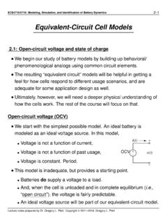
Equivalent-Circuit Cell Models
mocha-java.uccs.eduEquivalent-Circuit Cell Models 2.1: Open-circuit voltage and state of charge We begin our study of battery models by building up behavioral/ phenomenological analogs using common circuit elements. The resulting “equivalent circuit” models will be helpful in getting a feel for how cells respond to different usage scenarios, and are

CIRCUITS LABORATORY EXPERIMENT 3 AC Circuit Analysis
classes.engineering.wustl.eduThe phasor-domain equivalent circuit for the resistor circuit is shown in Figure 3.2 (a). If it is assumed that the current through the resistor is given by the phasor I = Im / θ , then the voltage across the resistor is V = R I = (R / 0o)(Im /θ ) = R Im /θ (3.8) from which we observe that there is no phase shift between the current and voltage.
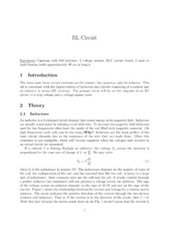
RL Circuit - New York University
physics.nyu.eduIf now V is set equal to 0 (this is equivalent to shorting the circuit) V L and V R will be given by V L = Ve t L=R and V R = Ve t L=R: (8) The response of an RLcircuit to an alternating pair of constant voltages, rst at V 0, and then 0, can be observed by applying a square wave to the circuit, alternating between V = V 0 and V = 0.
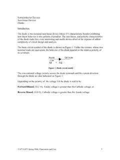
Figure 1. Diode circuit model - MIT OpenCourseWare
ocw.mit.educomplexity of circuit design and analysis. The basic circuit symbol of the diode is shown on Figure 1. Unlike the resistor, whose two terminal leads are equivalent, the behavior of the diode depend on the relative polarity of its terminals. Anode …
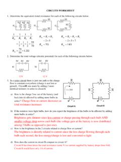
Circuit A Circuit B - Livingston Public Schools
www.livingston.orgCircuit A Circuit B, = 3 A CIRCUITS WORKSHEET 1. Determine the equivalent (total) resistance for each of the following circuits below. : 2. Determine the total voltage (electric potential) for each of the following circuits below. 13V 12 V 3. In a series circuit there is just one path so the charge flow is constant everywhere (charge is not lost or

Circuit Worksheet Solution - Birdville ISD / Overview
www.birdvilleschools.netCalculate the equivalent resistance of the following combination: R eq = 12/11 or 1.1 eq 3. Complete the table by calculating the total resistance of the following series circuit. Then calculate total circuit current and the voltage drops and currents for each of the resistors. V I R Source 12V 1A 12 R 1 2.0V ...
dependent sources - Iowa State University
tuttle.merc.iastate.eduThe circuit below uses a voltage-dependent voltage source to approximate the behavior of amplifier. The amplifier model consists of the resistors R 2 and R 3 and the dependent source. (We will study amplifiers in more detail soon.) In the circuit, find v R4. 0.1 V 1 k! 5 k! 100 ! 100 ! A = 100 Find an expression for v R4 using a voltage ...