Search results with tag "Equivalent circuit"

Thevenin / Norton equivalent circuits - Iowa State University
tuttle.merc.iastate.eduThevenin / Norton equivalent circuits We have seen many instances where we can take elements in a part of a circuit and combine them in some fashion to make an equivalent circuit. With respect to the two terminals, the two versions behave identically. Anything attaching to the two terminals will not be able to tell the difference. R eq = R 1 +R ...

Modeling and Simulation of Permanent Magnet Synchronous ...
www.irphouse.comIII Equivalent Circuit of Permanent Magnet Synchronous Motor Equivalent circuits of the motors are used for study and simulation of motors. From the d-q modeling of the motor using the stator voltage equations the equivalent circuit of the motor can be derived. Assuming rotor d axis flux from the permanent magnets
Dynamic Models for Wind Turbines and Wind Power Plants - …
www.nrel.govJan 11, 2008 · 3. Modeling of Variable-Slip (Type 2) Wind Turbine Generators. ... 3.1.1 Induction machine equivalent circuit 25 3.1.2 Effect of rotor resistance change on equivalent circuit and torque and power equations ... 4.4 Three-Phase Model: Steady-State Performance ...

Audio Amplifier Circuit - UC Santa Barbara
web.ece.ucsb.edu1.2 Speaker Equivalent Circuit 9 1.3 Assemble Amplifier on Breadboard 9 1.4 Summing network 11 1.5 Optional -- Tone-Control Circuit 12 1.6 Hardwire the Amplifier 13 1.7 Possible Improvements 14 Pre-lab Preparation Before Coming to the Lab Read through the lab experiment to familiarize yourself with the components and
Crystal Oscillators (XTAL) - University of California ...
rfic.eecs.berkeley.eduThe equivalent circuit contains series LCR circuits that represent resonant modes of the XTAL. The capacitor C 0 is a ... 1 are modeling parameters and not physical inductance/capacitance. The ... For the steady-state, ...
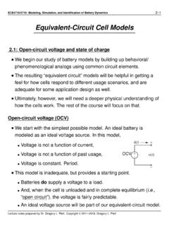
Equivalent-Circuit Cell Models
mocha-java.uccs.eduEquivalent-Circuit Cell Models 2.1: Open-circuit voltage and state of charge We begin our study of battery models by building up behavioral/ phenomenological analogs using common circuit elements. The resulting “equivalent circuit” models will be helpful in getting a feel for how cells respond to different usage scenarios, and are

CIRCUITS LABORATORY EXPERIMENT 3 AC Circuit Analysis
classes.engineering.wustl.eduThe phasor-domain equivalent circuit for the resistor circuit is shown in Figure 3.2 (a). If it is assumed that the current through the resistor is given by the phasor I = Im / θ , then the voltage across the resistor is V = R I = (R / 0o)(Im /θ ) = R Im /θ (3.8) from which we observe that there is no phase shift between the current and voltage.