Experiment The Oscilloscope
Found 10 free book(s)
The Oscilloscope and the Function Generator
courses.washington.edue ect experiment), or act as a timing signal, i.e., \clock" (phase-sensitive detection experiment). Oscilloscopes are a type of signal analyzer|they show the experimenter a picture of the signal, usually in the form of a voltage versus time graph. The user can then study this picture to learn

CIRCUITS LABORATORY EXPERIMENT 9 Operational Amplifiers
classes.engineering.wustl.eduEXPERIMENT 9 Operational Amplifiers 9.1 INTRODUCTION An operational amplifier ("op amp") is a direct-coupled, differential-input, high-gain voltage amplifier, usually packaged in the form of a small integrated circuit. The ... Use oscilloscope CH1 to measure Vi and CH2 to measure Vo. You may find it useful
Experiment 8: Capacitance and the Oscilloscope
www.columbia.eduIn this experiment you will study different RC circuits and observe their properties Main goals are: Use a timer to measure RC from the charge and discharge curve of a circuit with larger RC (slow) Familiarize with an oscilloscope Use the oscilloscope to study a circuit with small RC (fast)
Experiment #1: RC Circuits - University of California, San ...
courses.physics.ucsd.eduSpecifically you will use the multimeter and oscilloscope during this lab. Recall that the oscilloscope must be calibrated at the beginning of any experiment in which it is used. 1 Physics 1.1 Electrical Circuit Definitions Any section of a circuit that is at constant voltage is called a “node.” An example is a piece of wire

Experiment 2: Oscillation and Damping in the LRC Circuit
courses.physics.ucsd.eduExperiment 2: Oscillation and Damping in the LRC Circuit 1 Experiment 2: Oscillation and Damping in the LRC Circuit Introduction In this laboratory you will construct an LRC series circuit and apply a constant voltage over it. You will view the voltage drop over the various elements of the circuit with the oscilloscope. You must
EXPERIMENT #1 STUDY OF RC AND RL CIRCUITS
www.iium.edu.my27mH and C=1uF, oscilloscope and square-wave generator. Set up the RLC circuit as shown in Figure 1 Figure 1 Apply a 4.0 V (peak-to-peak) sinusoidal wave as input voltage to the circuit. Set the Source on Channel A of the oscilloscope, and the voltage across the ca[pcitance on Channel B of the oscilloscope.
Measuring relative phase between two waveforms using an ...
eeshop.unl.eduMeasuring relative phase between oscilloscope traces using the curvefitting method Requirements: Oscilloscope: • Dual channel capability • Capability to transfer data points to a computer This method was developed using the Tektronix 2012B oscilloscope. It has been implemented using OpenChoice Desktop software and an Excel spreadsheet called
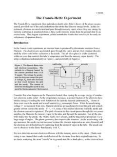
The Franck-Hertz Experiment - University of Michigan
instructor.physics.lsa.umich.eduJan 30, 2006 · The Franck-Hertz Experiment The Franck-Hertz experiment, first undertaken shortly after Bohr’s theory of the atom was pre-sented, provided one of the early indications that atoms had discrete energy levels. In this ex-periment, electrons are accelerated and pass through mercury vapor, where they lose energy by

Experiment 4: Amplitude Modulation - University of Texas ...
personal.utdallas.eduIn Experiment 3, DSB signals were generated by the multiplication of a message signal with a carrier waveform. This resulted in the translation of the message spectrum to the carrier frequency location. ... oscilloscope to the output of the modulator (at pin 7). 2. Turn the power supply on and capture the AM signal and its spectrum by executing ...

Experiment #5 Zener Diode Characteristics
www.uoanbar.edu.iqExperiment #5 Object To study and measure the effects of forward and reverse bias on the Zener diode current. To construct a Zener voltage regulator and experimentally determine the range over which the Zener maintains a constant output voltage. Required Parts and Equipment's 1. A Zener diode 2. Electronic Test Board (M50) 3. Dual-Channel ...