Guidelines For Printed Board Component Mounting
Found 8 free book(s)
LGA1150 Socket — Application Guide - Intel
www.intel.comThermal Mechanical Specifications and Design Guidelines 328906 Definition of Terms Table 2. Terms and Descriptions ... opening defines the pad size for soldering to the component to the printed circuit board. T CASE or TC The case temperature of the processor, ... balls for surface mounting on the motherboard.
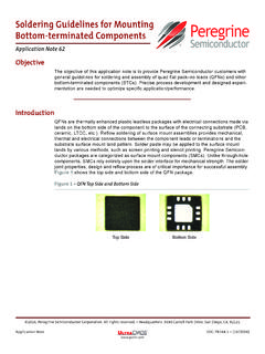
Soldering Guidelines for Mounting Bottom ... - pSemi
www.psemi.comfollow board design requirements based in IPC A-600—Acceptability of Printed Circuit Boards(1) and IPC 6012D—Qualification and Performance of Rigid Printed Boards(2). PCB Surface Finish Electroless nickel/electroless palladium/immersion gold (ENEPIG) is the preferred surface finish for the PCB copper land and pads.

VersaView 5000 ThinManager Thin ... - Rockwell Automation
literature.rockwellautomation.comBIOS Basic input/output system PCB Printed circuit board CF CompactFlash PCDC Product Compatibility and Download Center CMOS Complementary metal oxide semiconductor PCI Peripheral component interconnect COM Communication (serial port interface) PCIe Peripheral component interconnect express DDR Double data rate (RAM) PELV Protective extra-low ...
PCB Design Guidelines For Reduced EMI - Texas Instruments
www.ti.comthe third noise source has been addressed. Also, critical information is disclosed on board zoning (floor planning) and shieldi ng. 1.2 Surface-Mount Devices vs Through-Hole Components Surface-mount devices (SMD) are better than leaded devices in dealing with RF energy because of the reduced inductances and closer component placements available.
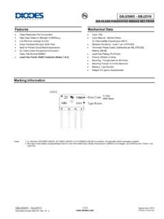
GBJ25005 - GBJ2510 - Diodes Incorporated
www.diodes.com• Glass Passivated Die Construction • High Case Dielectric Strength of 2500VRMS • Low Reverse Leakage Current • Surge Overload Rating to 350A Peak • Ideal for Printed Circuit Board Applications • UL Listed Under Recognized Component Index, File Number E94661 • Lead Free Finish; RoHS Compliant (Notes 1 & 2)

Generic Standard on Printed Board Design - IPC
www.ipc.orgallowance for edge printed board connector area, printed board guides, and printed board extractor.) ..... 18 Figure 3-6 Printed Board Density Evaluation ..... 20 Figure 4-1 HASL Surface Topology Comparison ..... 34 Figure 5-1 Example of Printed Board Size

PSP511Ca, LCa ENGLISH (Page 1) - LUX Products Pro Solutions
pro.luxproducts.comIf you are mounting the base to soft material like plasterboard or if you are using the old mounting holes, the screws may not hold. Drill a 3/16 in. (4.8mm) hole at each screw, and insert the plastic anchors provided. 4. Hold the base against the wall. Route the wires through the hole below the terminal block.
IPC-J-STD-001G: Requirements for Soldered Electrical and ...
www.ipc.orgIPC J-STD-001G Requirements for Soldered Electrical and Electronic Assemblies Developedby the J-STD-001Task Group(5-22a)of the Soldering Subcommittee(5-22) of the Assembly& JoiningCommittee(5-20)