Low Power Boost Converter
Found 5 free book(s)
Module 4: DC-DC Converters - NPTEL
nptel.ac.inregenerative braking is required. The power flow in a bi-directional converter is usually from a low voltage end such as battery or a supercapacitor to a high voltage side and is referred to as boost operation. During regenerative braking, the power flows back to the low voltage bus to recharge the batteries know as buck mode operation.
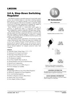
3.0 A, Step-Down Switching Regulator - ON Semiconductor
www.onsemi.com• Positive to Negative Converter (Buck−Boost) • Negative Step−Up Converters • Power Supply for Battery Chargers See detailed ordering and shipping information in the package dimensions section on page 23 of this data sheet. ORDERING INFORMATION 1 5 TO−220 TV SUFFIX CASE 314B 1 5 Heatsink surface connected to Pin 3 TO−220 T SUFFIX ...
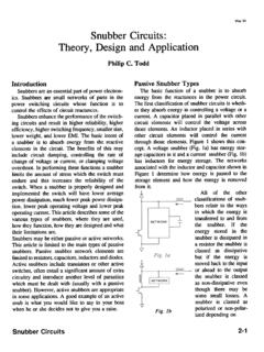
Snubber Circuits: Theory , Design and ... - Texas Instruments
www.ti.comenergy from the reactances in the power circuit. The fIrst classification of snubber circuits is wheth- ... high or the efficiency is too low. Table I -QUICK GUIDE TO SNUBBER CIRCUIT USAGE ... Figure 2 shows the basic buck, boost and flyback converter circuits drawn so that the switch is always grounded. The figures which follow will generally

3.0 A, 15 V, Step-Down Switching Regulator - ON …
www.onsemi.comSince the LM2576 converter is a switch−mode power supply, its efficiency is significantly higher in comparison with popular three−terminal linear regulators, especially with higher input voltages. In many cases, the power dissipated is so low that no heatsink is required or its size could be reduced dramatically.

Application of the MC34063 Switching ... - Texas Instruments
www.ti.comThe MC34063 was designed to be incorporated in buck, boost, or voltage-inverter converter applications. All these functions are contained in an 8-pin DIP or SOIC package. Figure 1. Functional Block Diagram The reference voltage is set at 1.25 V and is used to set the output voltage of the converter. Figure 2. Reference Voltage Circuit