Op Amp Input Impedance
Found 8 free book(s)
'Single-Supply Op Amp Design Techniques'
www.ti.comOutput impedance ZOUT 0 ... As long as the voltage on the op-amp input leads does not become negative, the circuit can handle negative input voltages. Beware of working with negative (positive) input voltages when the op amp is powered from a positive (negative) supply because op-amp inputs are highly
MT-038: Op Amp Input Bias Current - Analog Devices
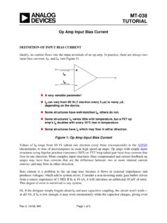
www.analog.comOp Amp Input Bias Current . DEFINITION OF INPUT BIAS CURRENT . Ideally, no current flows into the input terminals of an op amp. In practice, there are always two input bias currents, IB+ and IB-(see Figure 1). Rev.0, 10/08, WK Page 1 of 5 A very variable parameter! I B can vary from 60 fA (1 electron every 3 μs) to many μA,
MCP6001/1R/1U/2/4 - 1 MHz, Low-Power Op Amp
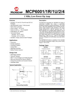
ww1.microchip.comMay 14, 2019 · VCM = Op Amp’s Common-Mode Input Voltage (V) VOST = Op Amp’s Total Input Offset Voltage (mV) VOST = VIN– – VIN+ VDD RG RF VM OUT CB2 RL CL VL CB1 100 k 100 k RG RF VP VDD/2 100 k 100 k 10 k 60 pF 100 nF …
Introduction Op Amp Topologies Op Amp Structures Op …
www.analog.comThe basic op amp hookup of Figure 1-2 below applies a signal to the (+) input, and a (generalized) network delivers a fraction of the output voltage to the (−) input terminal. This constitutes feedback , with the op amp operating in closed-loop fashion.

Demystifying Type II and Type III Compensators Using Op ...
www.ti.comFigure 1. Type I Compensator Using the Traditional Op-Amp This type of Op-Amp requires local feedback (between its output and inputs) to make it stable. Under steady DC conditions, both the input terminals are virtually at the same voltage level. This determines the output voltage setting. However, though both resistors of the voltage divider

INTEGRATOR AND DIFFERENTIATOR USING OP-AMP
ee.cet.ac.inINTEGRATOR AND DIFFERENTIATOR USING OP-AMP AIM To design and set up an integrator and differentiator circuit using op-amp. APPARATUS REQUIRED Power supply, CRO, function generator, bread board, op-amp, capacitor and resistors. THEORY INTEGRATOR Refer to the figure 1. This circuit performs the integration of the input waveform. The

A Single-Supply Op-Amp Circuit Collection
mil.ufl.eduThe solution is to ac-couple the signals to and from the op-amp stage. In this way, the input and output devices can be referenced to ground, and the op-amp circuitry can be referenced to a virtual ground. When more than one op-amp stage is used, interstage decoupling capacitors might become unnecessary if all of the following conditions are met:
Op Amps for Everyone Design Guide (Rev. B)
web.mit.eduthe op amp’s place in the world of analog electronics. Chapter 2 reviews some basic phys-ics and develops the fundamental circuit equations that are used throughout the book. Similar equations have been developed in other books, but the presentation here empha-sizes material required for speedy op amp design. The ideal op amp equations are devel-