Pulsed
Found 7 free book(s)
Basic Electronics - New York University
engineering.nyu.edupulsed DC. •A filter capacitor is used to smooth out the pulses. •Capacitor must be large enough to store sufficient charge so as to provide a steady current supply to the load: f is rectified signal’s frequency (120Hz). R C f Load 1/ Transistor • A three lead semiconductor device that acts as: ...
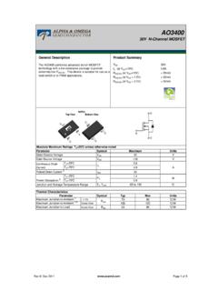
AO3400 Rev8 RoHS
aosmd.comPulsed Drain Current C Continuous Drain Current Gate-Source Voltage ±12 V Parameter Typ Max °C/W RθJA 70 100 90 TA=70°C 0.9 Junction and Storage Temperature Range -55 to 150 °C Thermal Characteristics Power Dissipation B PD TA=25°C …

Three-phase motor driver - STMicroelectronics
www.st.comIpeak Pulsed output current (1) 1. Pulse width limited only by junction temperature and the transient thermal impedance. 5 A VSENSE Sensing voltage (DC voltage) -1 to 4 V Vboot Bootstrap peak voltage 62 V VOD Differential output voltage (between any of the 3 OUT pins) 60 V fC Commutation frequency 150 kHz VREF Reference voltage 12 V

MC34152 - MOSFET Driver, High Speed, Dual
www.onsemi.com80 s Pulsed Load Figure 11. Drive Output Rise Time Figure 12. Drive Output Fall Time 10 ns/DIV 10 ns/DIV 90% - 10% - VCC = 12 V Vin = 0 V to 5.0 V CL = 1.0 nF TA = 25°C VCC = 12 V Vin = 0 V to 5.0 V CL = 1.0 nF TA = 25°C, OUTPUT CLAMP VOLTAGE (V), …
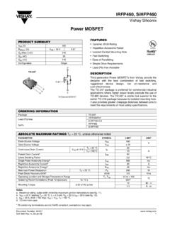
Power MOSFET - Vishay Intertechnology
www.vishay.comPulsed diode forward current a ISM-- 80 Body diode voltage VSD TJ = 25 °C, IS = 20 A, VGS = 0 Vb-- 1.8V Body diode reverse recovery time trr TJ = 25 °C, IF = 20A, dI/dt = 100 A/μsb - 570 860 ns Body diode reverse recovery charge Qrr-5.7 8.6μC Forward turn-on time ton Intrinsic turn-on time is negligible (turn-on is dominated by LS and LD) D ...

Complementary low voltage transistor - STMicroelectronics
www.st.com1. Pulsed: pulse duration = 300 µs, duty cycle 1.5% Collector-emitter sustaining voltage (IB=0) NPN IC = 30 mA BD135 BD139 45 80 V V PNP IC = -30 mA BD136 BD140-45-80 V V VCE(sat) (1) Collector-emitter saturation voltage NPN IC = 0.5 A, IB = 0.05 A 0.5 V PNP IC = -0.5 A, IB = -0.05 A -0.5 V VBE (1) Base-emitter voltage NPN IC = 0.5 A, VCE = 2 ...
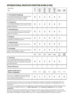
0 1 2 3 4 5 0 1 2 3 4 5 - BAUS
www.baus.org.ukThe I-PSS is based on the answers to seven questions concerning urinary symptoms. Each question is assigned points from 0 to 5 indicating increasing severity of the particular symptom.