Shear walls
Found 14 free book(s)
Chapter 12 SEISMIC DESIGN REQUIREMENTS FOR BUILDING …
www.ce.memphis.edushear walls with steel elements 14.3 6 21/2 5 NL NL 160 160 100 16. Ordinary composite reinforced concrete shear walls with steel elements 14.3 5 21/2 41/2 NL NL NP NP NP 17. Special reinforced masonry shear walls 14.4 51/2 21/2 4 NL NL 160 160 100 18. Intermediate reinforced masonry shear walls 14.4 4 21/2 4 NL NL NP NP NP 19. Ordinary ...

Design/Construction Guide: Diaphragms and Shear Walls
www.osbpanel.orgdiaphragms and shear walls are used in the lateral design of a building, the structural system is termed a “box sys-tem.” Shear walls provide reactions for the roof and floor diaphragms, and transmit the forces into the foundation. An accurate method for engi-neering diaphragms has evolved from analytic mod-els and extensive testing, and
APPENDIX C FOUNDATION CAPACITIES TABLES
www.hud.govshear walls to resist sliding in the transverse or longitudinal direction. See sections 602-5.G and 602-6.F. B. The roof/ceiling and floor of the super-structure are adequate as diaphragms, transfer-ring wind load to the transverse and longitudi-nal foundation shear walls. C. A home supported by piers does not
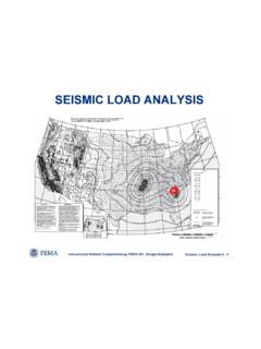
SEISMIC LOAD ANALYSIS - Memphis
www.ce.memphis.eduframes or are shear walls. • Diaphragms in one- and two-family residential buildings may be considered FLEXIBLE. • Concrete slab or concrete filled metal deck diaphragms are considered RIGID if the width to depth ratio of the diaphragm is less than 3 and if no horizontal irregularities exist. Diaphragms must be considered as semi-rigid unless
SIL211 MEKANIKA TANAH, 3(2-3) DESIGN AND DETAILING OF ...
web.ipb.ac.idOF RETAINING WALLS. 3 Gravity retaining wall GL1 GL2 Retaining walls are usually built to hold back soil mass. However, retaining wallscanalsobeconstructed for aesthetic landscaping purposes. RETAINING WALL BACK SOIL. 4 Batter Drainage Hole Toe Cantilever Retaining wall with shear key. Photos of Retaining walls 5.

DESIGN AND DETAILING OF RETAINING WALLS
engineeringcivil.comDesign of Shear key: If the wall is not safe against sliding, then a shear key is to be provided. It is provided either below the stem or at the end of heel. It should not be provided at the end of toe. If shear key is provided, then it should be designed taking the effect of passive pressure.

TM 5-809-3 Masonry Structural Design for Buildings
www.wbdg.org5-2. Equivalent Wall Thickness for Computing Compression and Shear Stress Parallel to the Wall for Hollow Concrete Masonry Units, Inches. 5-3. Area Effective in Axial Compression and in In-Plane Shear, A e, in2/ft. 5-4. Gross Moment of Inertia and Cracking Moment Strength for Various Widths of CMU Walls. Type S Mortar, f' m = 1350. 5-5.

Beam Bending Stresses and Shear Stress
faculty-legacy.arch.tamu.eduEven vertical connectors have shear flow across them. The spacing can be determined by the capacity in shear of the connector(s) to the shear flow over the spacing interval, p. Unsymmetrical Sections or Shear If the section is not symmetric, or has a shear not in that plane, the member can bend and twist. If the load is applied at the shear center

Live Loads for Bridges - Memphis
www.ce.memphis.eduFirst we need the influence line for the shear at point C. A 50 ft.C B Using the Muller-Breslau principle construct the influence line for the shear at point C V VC x V The change in shear is equal to 1 Live Loads for Bridges 0.5-0.5 A 50 ft. B 50 ft. 14 ft. 30 ft. 8 k 32 k 32 k Let’s try to find the maximum positive shear at point C.

A Design Example for a Rectangular Concrete Tank PCA ...
civil.colorado.eduThe maximum shear in the wall is obtained from the maximum shear coefficient from page 2-17 of PCA-R, in this case Cs = 0.50. The wall will be designed for the concrete to resist the entire shear force. For the shear calculation qu = (1.0)(1.7)(945 pcf) = 1,607 psf Vu = Cs × qu Note:
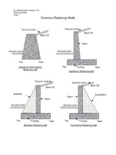
Common Retaining Walls - Texas A&M University
people.tamu.eduRetaining Walls Page 10 Lateral Soil Pressure on Retaining Walls Typical Angle of Internal Friction for backfill soil Soil Type φ (Degree) Gravel and coarse sandy backfill soil 33-36 Medium to fine sandy backfill soil 29-32 Silty sand 27-30 P max = K a γ soil h h γ soil Backfill Fig. 1: Soil Pressure on the back of wall (No surcharge)
A Design Example for a Rectangular Concrete Tank PCA ...
civil.colorado.edu1.0 shear provided by concrete 1.3 for shear beyond that provided by concrete Another change is the fluid load factor is 1.7 rather than 1.4 as stated in the ACI specification. For the purposes of this class, the following load combinations and factors will be used: Mu = 1.3(1.4D + 1.7F + 1.6H) for flexure
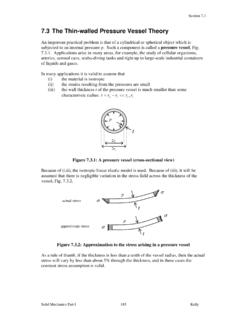
7.3 The Thin-walled Pressure Vessel Theory
homepages.engineering.auckland.ac.nzstress normal to the walls of the sphere is called the radial stress, r. The radial stress is zero on the outer wall since that is a free surface. On the inner wall, the normal stress is r p, Fig. 7.3.5. From Eqn. 7.3.3, since t/r 1, p t, and it is reasonable to
Manual for the design of reinforced concrete building ...
timurdhaka.weebly.comConstitution D J LeeCBE BScTech DIC FEng FIStructE FICE Chairman, (until April 1995) (previously G Maunsell & Partners) R S Narayanan BE(Hons) MSc DIC FEng FIStructE Chairman, (from May 1995) (S B Tietz & Partners) ProfessorAWBeebyBSc(Eng) PhD CEng MIStructE MICE (University of Leeds) PG CobbCEng MICE (Sir Robert McAlpine & Sons Ltd)