Transcription of APPENDIX C FOUNDATION CAPACITIES TABLES
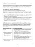
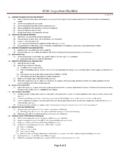
1 APPENDIX C FOUNDATION CAPACITIES TABLES C-100. USE OF FOUNDATION CAPACITIES TABLES . GENERAL. The FOUNDATION Ca-pacities TABLES provide FOUNDATION design ca-pacities and dimensions for three conditions of FOUNDATION design. A. Withdrawal Resistance. The ability of a FOUNDATION wall or pier plus its respective footing to resist uplift and overturning. See TABLES C-1 & C-2. B. Vertical Anchor Capacity. The re-quired size and spacing of anchors to tie the superstructure to the FOUNDATION to meet the required uplift or overturning in the transverse direction. See TABLES C-3 & C-4 (a & b). C. Horizontal Anchor Capacity. The required size and spacing of anchors to tie the superstructure to the FOUNDATION to resist slid-ing in the transverse and longitudinal directions - Horizontal Anchor Capacity Table, Table C--5.
2 CONNECTIONS of the FOUNDATION to the manufactured home is dependent on the rated capacity of the manufacturer's connection designs. C-200. WITHDRAWAL RESIS-TANCE CAPACITY TABLES . There are two TABLES providing the withdrawal resis-tance (uplift and overturning) for different de-signs of FOUNDATION walls and piers on spread footings at different depths. LONGITUDINAL FOUNDATION walls . The "Withdrawal Resistance for Longitudinal FOUNDATION walls - Table C-1 is used for manufactured homes anchored to lon-gitudinal FOUNDATION walls , specifically system type E. The table provides a footing width and depth below grade to prevent uplift. Example: Determine the withdrawal resistance of a 6 reinforced concrete wall with a height (hw) of 3 - 4 and with a 6 x16 footing.
3 Re-peat for a 6 CMU wall grouted solid, then grouted at 48 , and lastly for an all-weather wood FOUNDATION . Solution: Start with the concrete wall: wall weight: ( ) ( ) 150 pcf = 250 plf; reinforced concrete footing weight: (6 16 ) 150pcf = 100 plf; rectangular soil wedge wt: ( -1 ) ((16 6 ) (2 12 )) 120pcf = 116 plf. The total withdrawal resistance is the sum of the wall, footing and soil block weight, which is 250+100+116 = 466 plf. This matches the ta-bled value. The solid grouted CMU wall: wall wt.: ( ) (63 psf) = 210 plf, 16 footing and 5 soil wedge calculations are the same as above.
4 The total withdrawal is the sum = 210 + 100 + 116 = 426 plf, just as found in the Table. The partially grouted CMU wall: wall wt.: ( ) (45psf) = 150 plf, 16 footing and 5 soil wedge are the same. The total withdrawal is the sum = 150+100+116 = 366 plf, just as found in the table. Lastly, for the all-weather wood FOUNDATION : wood stud wall wt.: 2 x6 plate = plf; (3)-2 x4 plates = 3 plf = plf; 2 x4 @ 16 = psf = ; 1/2 plywood = = C - 1 plf. Wood sum = + + + = plf; footing weight is the same as caculated before. Soil weight is based on a 6 wide wedge: ( ) (16-4) (2 12) pcf = 140 plf. Total withdrawal = +100+140 = 254 plf, just as in the Table.
5 PIER FOUNDATIONS. The "Withdrawal Resistance for Piers - Table C-2 is used for manufactured homes anchored to piers; specifically system Types C, I, and Type E when interior piers are used for anchorage. This table also applies to the concrete tie-down block for type C1 foundations. Example: Determine the withdrawal resistance of a 3 foot square footing with an 8 x16 solid grouted CMU pier of a height (hp) of 3 -4 . Grade exists 12 inches down from the top of the pier. Solution: Assume the following material weights: 8 CMU = 84 psf; soil = 120 pcf; and concrete = 150 pcf. Pier weight = (84psf) (16/12) ( ) = 373 weight = (150pcf) (8/12) (3 3 ) = 900 lbs.
6 Assume footing perimeter creates a conservative shear plane. Soil above footing also counted to resist withdrawal. Soil Weight = (120pcf) ( -1 ) (32 - (8) (16)/144) = 2267 lbs. Total with-drawal resistance is the sum of the pier + foot-ing + soil = 3541 lbs. This magnitude matches the value found in the Table C-2. FOOTING DEPTH. The bottom of the footings must be below the maximum frost depth for the area where the home is located. Example: The average depth of frost penetra-tion is 35 inches. Assume that the required footing depth to resist withdrawal (Av) is hw = 2 feet. The depth of the base of the foot-ing is 24"-12"+6"=18". This is less than 35".
7 The depth of hw must be increased to 41" in order for the base of the footing to be at 35"--the required depth to prevent frost damage & also satisfy withdrawal requirements (41"-12"+6"=35"). C-300. VERTICAL ANCHOR CA-PACITY TABLES provide the required anchor and reinforcing size and spacing to tie the superstructure to the FOUNDATION wall or piers. As in section above, there are two Vertical Anchorage Capacity TABLES , one for longitudinal FOUNDATION walls and one for piers. PIERS. The Vertical Anchor Ca-pacity for Piers - Table C-3 is used for manu-factured homes anchored to piers to prevent uplift specifically system Types C, I, and Type E when interior piers are used for anchorage (multi-section E's).
8 Example: Anchor bolts are assumed to be made from A36 rod stock and of embedment length sufficient to fully develop the allowable tensile capacity ( Fy) of the diameter of rod used. A 1/2 diameter anchor bolt has the following capacity: ( 36,000psi) ( ) = 4,240 psi, as noted in the Table. The capacity of any substituted grade of steel can easily be calcu-lated if the yield point and diameter are known. LONGITUDINAL CON-CRETE/MASONRY FOUNDATION walls . The Vertical Anchorage Capacity for Longitudinal FOUNDATION walls - Table C--4A is used for manufactured homes anchored to a continuous Reinforced concrete or rein-forced concrete masonry FOUNDATION wall, spe-cifically system Type E.
9 Example: Determine the anchorage capacity per foot of FOUNDATION wall if 1/2 diameter an-C - 2 chor bolts are spaced 3 -4 and attach to a continuous treated wood mud sill 1-1/2 thick. Standard washers are used under the nut and bear into the mud sill perpendicular to grain. Solution: Determine the bearing area of a stan-dard washer with = and = : Abrg = ( - ) 4 = sq. in.. The capacity in bearing multiplied by a bearing area factor Cb = Thus, the bearing capacity = 565 psi = 873 bolt. The capacity for a given spacing of bolts is found by division of that spacing. Thus, for a 3 -4 bolt spacing: 873 = 262 plf, which is the same as in the Table.
10 Use of an oversized washer (for a 5/8 dia. bolt) produces a larger capacity per bolt. The = and the = , thus the net bearing area : Abrg = ( - ) 4 = The vertical anchor capacity at the same same spacing = 565 psi = 431 plf, which is the same as in the Table. LONGITUDINAL TREATED WOOD FOUNDATION walls . The Ver-tical Anchorage Capacity for Longitudinal FOUNDATION walls - Table C-4B is used for manufactured homes anchored to a continuous treated wood FOUNDATION wall, specifically sys-tem Type E. Vertical anchorage CAPACITIES are based on the use of standard washers over 1/2 dia. bolts.