Standard Switch Circuit Diagrams
Found 11 free book(s)
A-1 HOW TO READ THE WIRING DIAGRAMS - Evoscan
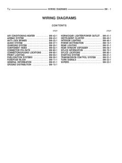
www.evoscan.comCircuits from the battery to fusible link, dedicated fuses, ignition switch, general purpose fuses, etc. D Circuits classified by system For each system, the circuits are shown from fuse to earth, excluding the power supply sections. D Operation The standard operation of each system is briefly described, following the route of current flow.

PARTS LISTINGS & WIRING DIAGRAMS for the HURCO …
www.hurco.comcircuit boards, switches, fuses, cables, or components within the Power and/or control cabinets. • Whenever working in an area away from the disconnect switch, post a warning on or near the switch telling others not to turn ON the power to the machine.

TERMINAL MARKINGS AND INTERNAL WIRING DIAGRAMS …
www.rses.orgIt has been found to be impracticable to follow this standard for the lead markings of : some definite-purpose motors. See Part 18.† MG 1-2.42 Auxiliary Devices Within Motor . The presence of an auxiliary device or devices, such as a capacitor, starting switch, terminal protector,

PWRview™ Owner’s Manual - Generac Power Systems
www.generac.comA 200A rated switch is suitable for use on a circuit capable of 22,000 RMS symmetrical amperes, 240 VAC when protected by a circuit breaker without an adjustable short time response or by fuses. Figure 2-1. Typical Single-Phase ATS Transfer Mechanism Utility Service Circuit Breaker (if equipped) The utility service circuit breakers for 200 amp ...
WIRING DIAGRAMS - uCoz
gershon.ucoz.comorder to effectively use Chrysler wiring diagrams to diagnose and repair a Chrysler vehicle, it is impor-tant to understand all of their features and charac-teristics. Diagrams are arranged such that the power (B+) side of the circuit is placed near the top of the page, and the ground (B-) side of the circuit is placed near the bottom of the page.
Info card Operating voltage The voltage range in ... - ifm
www.ifm.comSwitch point drift The shifting of the switch point owing to changes in the ambient temperature. Switching frequency Damping with standard target at half Sn. The ratio damped to undamped (tooth to gap) = 1 : 2. 2a a a S n 2 Protection rating IPxy According to IEC 60529 IP68 Test condition: 1 m water depth for 7 days

Wiring & Vacuum Diagrams - Forel Publishing
www.forelpublishing.comIn the wiring diagrams from the Ford publication Form 7795P-71, the Key Warning Buzzer Wiring Color Code shows: 38 Black. However, the Car Standard Wire Color Code Chart lists: 38 – Black-Orange Stripe. In the wiring diagrams from the Ford publication Form 7795P-71, the Key Warning Buzzer Wiring Color Code shows: 158 Black-Pink HASH STRIPE
TERMINAL MARKINGS AND INTERNAL WIRING …
www.rses.orgIt has been found to be impracticable to follow this standard for the lead markings of : some definite-purpose motors. See Part 18.† MG 1-2.42 Auxiliary Devices Within Motor . The presence of an auxiliary device or devices, such as a capacitor, starting switch, terminal protector,

Switch Ratings, What's it all Mean? - AEROELECTRIC.COM
www.aeroelectric.comcircuit ve rsus an AC circuit . . . particularly when inductive loads are involved. Quoting from the article: "Typical of this is the roller and bar micro switches made by MICRO(switch) Corporation. Rated at 10 amps for 125/250 volt AC, the same switch c an only carry 0.15 amps at 250 volts DC! The voltage stayed the same!"

An Overview of: NFPA 86 Standard for Ovens and Furnaces
ovens.lewcoinc.comStandard for Ovens & Furnaces Introduction The most widely referenced standard in the United States for industrial heat processing equipment is the National Fire Protection Agency (NFPA) 86 Standard for Ovens and Furnaces. This standard is updated on a regular basis with the latest revisions happening in 2015.

TLSZR/L-GD2 Guard Locking Switch - Rockwell Automation
literature.rockwellautomation.comIf power is supplied to the switch and the switch is in the locked state, operation of the auxiliary release causes the switch to enter a fault condition (blinking red light-emitting diode). To reset the switch, cycle the power. A manual release is possible by removing the secure Torx screws and pressing the internal mechanism.