Search results with tag "Keyway"

Standard Bore and Keyway Tolerances (Inch and mm)
www.pfeiferindustries.comKeyway Bore Diameter Size Bore Reference -0.000 / +0.010 Height (d) (t) - DIM Keyway Width (w) AGMA 9002-A86 Inch Bore and ANSI B17.1 Square Keyway Tolerances Minimum 3.0000 0.7500 3.332 Maximum 3.0015 0.7530 3.342 Minimum 3.0625 0.7500 3.396 Maximum 3.0640 0.7530 3.406 Minimum 3.1250 0.7500 3.459 Maximum 3.1265 0.7530 3.469 Minimum 3.1875 0 ...

2.5 Chain drive systems - Gears EdS
www.gearseds.comThe flange has a keyway (groove) that is cut into the bore. This keyway matches up to a similar keyway cut into the shaft. A rectangular or square “Key” is inserted into the two keyways and prevents unwanted rotation of the shaft. Fig. 9 Type A …
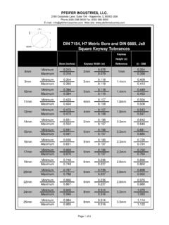
Standard Bore and Keyway Tolerances (Inch and mm)
www.pfeiferindustries.comKeyway Bore (inches) Reference Height (d) 1.8mm 1.8mm 2.3mm 2.3mm 2.3mm 2.3mm 2.8mm 2.8mm 2.8mm 3.3mm 3.3mm 5mm 5mm 5mm 5mm 6mm 6mm 6mm 8mm 8mm 22mm 24mm 16mm 17mm 19mm 20mm 25mm Keyway Width (w) 10mm 3mm 3mm 1.4mm 1mm 1.4mm 8mm 2mm 9mm 12mm 11mm 4mm 4mm 14mm 15mm DIN 7154, H7 Metric Bore and DIN 6885, Js9 …

Understanding Electric Motor Nameplates
www.egr.msu.edukeyway or slot in the motor shaft. The first dimension will be the width of the keyway which is the dimension of the key needed. For example, the keyway dimension may be shown as 3/16 × 3/32. This means that the key way is 3/16 in. wide which requires a key that is 3/16 in. square.

Shaft and Hub Keyway and Key Sizes
dpk3n3gg92jwt.cloudfront.netMetric Standard Parallel Keyway and Key Sizes Shaft Diameter (mm) Keyway (mm) Key (mm)* From To Width (W) Depth (h) Width (W) Depth (T) 6 8 2 1.0 2 2 9 10 3 1.4 3 3 11 12 4 1.8 4 4 13 17 5 2.3 5 5 18 22 6 2.8 6 6 23 30 8 3.3 8 7 31 38 10 3.3 10 8 39 44 12 3.3 12 8 45 50 14 3.8 14 9

Couplings - Renold
www.renold.comKeyway and Keyway Dimensions 14 Taper Bushes 15. Spiderflex 16 Spider 19. Pinflex 20 Crownpin 25. Tyreflex 28 Discflex 31. Chainflex 34 Rigid 36. Gearflex 37 ... Bore and key (mm) Torsionally Flexible Spiderflex (RSC) +1.7 2.5 0.5 32 – 3,150Nm ...
Shaft and Hub Keyway and Key Sizes - Micro-Machine-Shop
www.micro-machine-shop.com17656-3 Shaft and Hub Keyway and Key Sizes Keys connecting shafts to pulley hubs are commonly used to achieve reliable no-slip power transmission in belt drive systems.
General Instructions for 3-Keyway Crank Sprockets - Cloyes
www.cloyes.comFebruary 2, 2009 © Copyright 2009, Cloyes Gear & Products, Inc. All rights reserved Installation Instructions Cloyes ® 3-Keyway Crank Sprockets The Cloyes ...
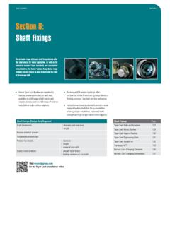
Section 6: Shaft Fixings
www.fptgroup.com130 Taper Lock® Imperial Bushes Section : 6 Shaft fixingS Bore Dia keyway Shallow keyway Depth Product code Width Depth 3525 3535 4030 4040 4535 4545 5040 5050 1.500 0.375 0.11 – 019J0108 019R0108 1.625 0.437 0.13 – 019J0110 019R0110 1.750 0.437 0.13 – 019J0112 019R0112 019X0112 19S0112 1.875 0.500 0.13 – 019J0114 019R0114 019X0114 19S0114 …

Bore Key Sheets - dpk3n3gg92jwt.cloudfront.net
dpk3n3gg92jwt.cloudfront.netBore tolerances per BS 4500 H7 fit. 2. Keyway width tolerances per BS 4235 P9 fit. 3. Keyway depth and fillet radius per BS 4235. 4. All dimensions are in millimeters. 5. Actual shaft fit will vary depending on actual shaft diameters.

ANSI-B17.1 Keyway Dimensions
www.lowellcorp.comANSI-B17.1 Size Shaft Dia. Size Shaft Dia. 3/8 .375 / .376 .093 / .095 .432 / .442 2-5/16 2.312 / 2.314 .625 / .628 2.587 / 2.597 7/16 .437 / .438 .093 / .095 .493 ...
Standard Bore and Keyway Tolerances (Inch and mm)
www.pfeiferindustries.comPFEIFER INDUSTRIES, LLC. 2180 Corporate Lane, Suite 104 ~ Naperville, IL 60563 USA Phone (630) 596-9000 Fax (630) 596-9002 E-mail: info@pfeiferindustries.com Web site: www.pfeiferindustries.com

CHAIN COUPLINGS - Tsubaki
tsubaki.euFit Bore Series ̶See page 7̶ TSUBAKI offers 117 dimensions of standard bore processing and deliver them within a short time in response to orders. The standard tolerance of bore processing is based on H7 and support to the tolerances of press fitting too. Keyway tolerances are in conformity with new JIS Js9 and P9 and old JIS F7 and E9.

ROTEX GS - KTR
www.ktr.com4.3 Advice for finish bore 23 4.4 Assembly of the hubs (hub type 1.0, 1.1 and 1.2) 24 ... Hubs, clamping hubs or similar types without feather keyway may be used in category 3 only and are marked with category 3 accordingly. 2) Hub type 1.2 is …
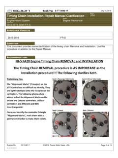
Timing Chain Installation Repair Manual Clarification
static.nhtsa.govKeyway is pointing straight down and the triangle alignment marks on the intake and exhaust controllers are pointing at each other ON BOTH BANKS (see the photo below the illustration). Remove the Bank 1 Timing Chain guide tensioner and guides, and remove the Bank 1 Chain.

Taper-Lock Bushing Installation and Removal
dpk3n3gg92jwt.cloudfront.netNote: Do not lubricate the bushing taper, hub taper, bushing bore, or the shaft. Doing so may result in sprocket/sheave hub fracture. DO NOT USE LUBRICANTS 4. With the key resting in the shaft keyway, position the sprocket/sheave and bushing assembly onto the shaft allowing for small axial movement of the sprocket/sheave which will occur during
Shaft and Hub Keyway and Key Sizes
dpk3n3gg92jwt.cloudfront.netmating shaft. Set screws do push shafts to one side of the bores causing eccentricity or radial run-out, resulting in belt tension excursion and vibration. In order to minimize these potentially negative results, Gates publishes recommended shaft to bore fit …

600H-600NH series
www.farnell.comINSULATED LEVER - DOUBLE POLE * Function 4 : SP in DP case - see "Technical information" on website KEYWAY III 2-1 5-4 II I 2-3 5-6 Solder lug Screw A 641NH/2 641NH 26° ON - OFF 644NH/2 644NH* 30° ON ON ON 644NH/2-1R 644NH-1R* 26° ON ON MOM 644NH/2-2R 644NH-2R* 26° MOM ON MOM 645NH/2 645NH 26° MOM - ON 646NH/2 646NH 26° ON - …
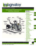
Magnaloy Products Catalog North America’s Favorite Source ...
www.magnaloy.comTOLERANCES: 2 Place Decimals ± .01 3 Place Decimals ± .001 TOLERANCES: 2 Place Decimals ± .01 ... Standard Bore and Keyway Combinations Magnaloy “Standard” Bore Key Combinations Model Bore/Key Code Code Model 100 200 300 400 500 600 700 800 Bore Key 900 M _ _ _ 01203

Keyway and Key Size Dimensions - ISC Companies
www.isccompanies.comMetric Standard Parallel Keyway and Key Sizes Shaft Diameter (mm) Keyway (mm) Key (mm)* From To Width (W) Depth (h) Width (W) Depth (T) 6 8 2 1.0 2 2 9 10 3 1.4 3 3 11 12 4 1.8 4 4 13 17 5 2.3 5 5 18 22 6 2.8 6 6 23 30 8 3.3 8 7 31 38 10 3.3 10 8 39 44 12 3.3 12 8 45 50 14 3.8 14 9 51 58 16 4.3 16 10 59 65 18 4.4 18 11 66 75 20 4.9 20 12 76 86 ...
Similar queries
Bore and Keyway Tolerances, Keyway Bore, Bore, Keyway, Keyway Tolerances, Key way, Parallel Keyway, Shaft and Hub Keyway and Key Sizes, Instructions, 3-Keyway Crank Sprockets, Bore tolerances, TOLERANCES, ANSI, Keyway Dimensions, Standard Bore and Keyway Tolerances Inch, Taper-Lock, Shaft, Vibration, Bore and Keyway