Search results with tag "Axially loaded"
3. AXIALLY LOADED MEMBERS - University of …
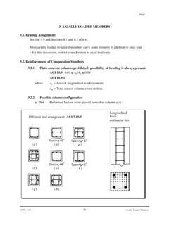
www.ce.memphis.edupage CIVL 4135 36 Axially Loaded Members 3. AXIALLY LOADED MEMBERS 3.1. Reading Assignment: Section 1.9 and Sections 8.1 and 8.2 of text.. Most axially loaded structural members carry some moment in addition to axial load

EN 1995-1-1: Eurocode 5: Design of timber structures ...
www.phd.eng.br8.3.2 Axially loaded nails 8.3.3 Combined laterally and axially loaded nails 8.4 STAPLED CONNECTIONS 8.5 BOLTED CONNECTIONS 8.5. 1 Laterally loaded bolts 8.5.1.1 General and bolted timber-to-timber connections 8.5.1.2 Bolted panel-to-timber connections 8.5.1.3 Bolted steel-to-timber connections 8.5.2 Axially loaded bolts
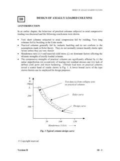
DESIGN OF AXIALLY LOADED COLUMNS
www.steel-insdag.orgDESIGN OF AXIALLY LOADED COLUMNS Universal Column (UC) sections have been designed to be most suitable for compression members. They have broad and relatively thick flanges, which avoid the problems of local buckling. The open shape is ideal for economic rolling and facilitates easy beam-to-column connections.
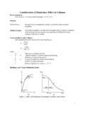
Consideration of Slenderness Effect in Columns
www.ce.memphis.edu3 Evaluation of the "k" Coefficient Figure 2. Buckling and Effective Length of Axially Loaded Columns. Comments on Axially Loaded Columns • A column might be considered short under some load conditions and end conditions, slender under others. • Columns braced against side sway have effective length between 0.5L and L. Columns
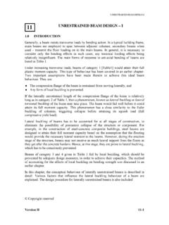
UNRESTRAINED BEAM DESIGN – I
www.steel-insdag.orgIt is well known that slender members under compression are prone to instability. When slender structural elements are loaded in their strong planes, they have a tendency to fail by buckling in their weaker planes. Both axially loaded columns and transversely loaded beams exhibit closely similar failure characteristics due to buckling.

Prof. Suvranu De Linear shape functions in 1D Quadratic ...
homepages.rpi.eduAxially loaded elastic bar x y x=0 x=L A(x) = cross section at x b(x) = body force distribution (force per unit length) E(x) = Young’s modulus x F Potential energy of the axially loaded bar corresponding to the exact solution u(x) dx bu dx Fu(x L) dx du EA 2 1 (u) 0 0 2 ⎟ − − = ⎠ ⎞ ⎜ ⎝ ⎛ ∫ L L Finite element formulation ...
Measurement of Strain Due to Bending and Axial Loads
www.ae.utexas.edufor a tip-loaded cantilever will be measured. The results for the differing measurement approaches will be compared with each-other as well as with theoretical values. A tensile specimen will be axially loaded in an Instron load cell. Strain calculations based on strain gage

CIVIL FORMULAS - Engineering Surveyor
engineeringsurveyor.comDesign of Axially Loaded Steel Columns / 102 v. Chapter 4. Piles and Piling Formulas 105 Allowable Loads on Piles / 105 Laterally Loaded Vertical Piles / 105 Toe Capacity Load / 107 Groups of Piles / 107 Foundation-Stability Analysis / 109 Axial-Load Capacity of Single Piles / 112

Disc Springs - SPIROL
www.spirol.comaxially loaded. What makes Disc Springs unique is that based on the standardized calculations of DIN EN 16984 (formerly DIN 2092), the deflection for a given load is predictable and the minimum life cycle can be determined. Disc Springs can be statically loaded either continuously or intermittently, or dynamically subjected to
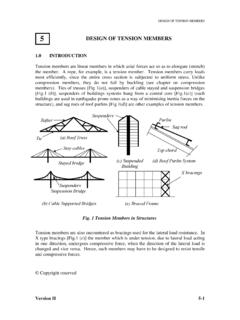
5 DESIGN OF TENSION MEMBERS - steel-insdag.org
www.steel-insdag.orgSince axially loaded tension members are subjected to uniform tensile stress, their load deformation behaviour (Fig.3) is similar to the corresponding basic material stress strain behaviour. Mild steel members (IS: 2062) exhibit an elastic range (a-b) ending at yielding (b). This is followed by yield plateau (b-c).
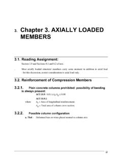
D. Chapter 3. Compression - Memphis
www.ce.memphis.eduMost axially loaded structural members carry some moment in addition to axial load - for this discussion, restrict consideration to axial load only. 3.2. Reinforcement of Compression Members 3.2.1. Plain concrete columns prohibited: possibility of bending is always present:
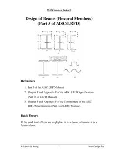
Design of Beams (Flexural Members) (Part 5 of AISC/LRFD)
user.engineering.uiowa.eduThe compressive flange of a beam behaves like an axially loaded column. Thus, in beams covering long spans the compression flange may tend to buckle. However, this tendency is resisted by the tensile flange to certain extent. The overall effect is a phenomenon known as lateral torsional buckling, in which the beam tends to twist and
2. Design of Welded Connections - American Welding Society
app.aws.orgin lap joints transferring stress between axially loaded parts shall be double-fillet welded (see Figure 2.5) ex-cept where deflection of the joint is sufficiently re-strained to prevent it from opening under load. 2.4.8.2 Minimum Overlap. The minimum overlap of parts in stress-carrying lap joints shall be five times
MECHANICS OF CHAPTER 1MATERIALS - IIT Bombay
www.civil.iitb.ac.in• The resultant of the internal forces for an axially loaded member is normal to a section cut perpendicular to the member axis. A P A F ave A 0 lim • The force intensity on that section is defined as the normal stress. • The detailed distribution of stress is statically indeterminate, i.e., can not be found from statics alone.
Light Steel Framing Design Standards
lpe.ku.edu• W104-10, Top Track Load Distribution Members • W105-13, Design of Nonstructural Members • W106-16, Design for Splicing of CFS Wall Studs • W200-09, Header Design • W400-16, Mechanical Bridging and Bridging Anchorage of Axially Loaded CFS Studs • W500-12, Construction Bracing for Walls

Technical Manual 1 Design of Monopole Bases
www.towernx.comThe AISC method for designing axially loaded base plates defines the critical section as being at .95 times the depth of the structural members for shapes of rectangular cross-section such as wide flanges and tubes. The critical section for pipe is defined at a location equal to .80 times the diameter of the pipe.

Mechanics of Materials - University of Pittsburgh
sites.pitt.eduDeformation of axially loaded members. Department of Mechanical Engineering. Stress vs. strain relationship ...
CHAPTER 3. COMPRESSION MEMBER DESIGN 3.1 …
www.egr.msu.eduBuckling of axially loaded compression members • The critical buckling load Pcr for columns is theoretically given by Equation (3.1) Pcr = ()2 2 K L π E I (3.1) where, I = moment of inertia about axis of buckling K = effective length factor based on end boundary conditions • Effective length factors are given on page 16.1-189 of the AISC ...
6 INTRODUCTION TO COLUMN BUCKLING - steel-insdag.org
www.steel-insdag.orgThis single plot can be employed to define the strength of all axially loaded, initially straight columns irrespective of their E and fy values. The change over from plastic yield to elastic critical buckling failure occurs when λ=1(i.e. when fy = σcr), the fy E is r ⎟ π ⎠ ⎞ ⎜ ⎝ ⎛λ corresponding slenderness ratio

Structural Analysis Equations
www.fpl.fs.fed.usThe deformation of an axially loaded member is not usually an important design consideration. More important con-siderations will be presented in later sections dealing with combined loads or stability. Axial load produces a change of length given by (9–1) where d is change of length, L length, A cross-sectional
Design of Beams (Flexural Members) (Part 5 of AISC/LRFD)
user.engineering.uiowa.eduThe compressive flange of a beam behaves like an axially loaded column. Thus, in beams covering long spans the compression flange may tend to buckle. However, this tendency is resisted by the tensile flange to certain extent. The overall effect is a phenomenon known as lateral torsional buckling, in which the beam tends to twist and
CE 405: Design of Steel Structures – Prof. Dr. A. Varma ...
www.egr.msu.edu• Stress: The stress in an axially loaded tension member is given by Equation (4.1) A P f = (4.1) where, P is the magnitude of load, and A is the cross-sectional area normal to the load • The stress in a tension member is uniform throughout the cross-section except: - near the point of application of load, and
Glulam Design Properties and Layup Combinations
harvest-timber.comAxially Loaded Members For members stressed primarily in axial tension or axial compression, where the stresses are uniform over the cross-section of the member, single-grade ... columns, a bending member combina-tion as tabulated in Table 1 …

Fatigue - Michigan State University
www.egr.msu.edureversed axially loaded, steel, hot-rolled surface Find: S n(2x10⁵ life cycles) Fatigue Strength Fluctuating stress = static stress + completely reversed stress mean + alternating Effect of mean stress. Fatigue Strength Effect of mean stress Static tensile stress reduces amplitude of …