Search results with tag "Sr latch"
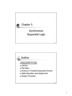
Chapter 5 Synchronous Sequential Logic
www.cse.iitb.ac.inSR Latch with Control Input! Add an additional control input to determine when the state of the latch can be changed! C=0: S and R are disabled (no change at outputs)! C=1: S and R are active-high 5-12 D Latch! D latch has only two inputs: D(data) and C(control)! Use the value of D to set the output value! Eliminate the indeterminate state in ...

7. Latches and Flip-Flops - University of California ...
www.cs.ucr.eduChapter 7 – Latches and Flip-Flops Page 3 of 18 a 0. When both inputs are de-asserted, the SR latch maintains its previous state. Previous to t1, Q has the value 1, so at t1, Q remains at a 1. Similarly, previous to t3, Q has the value 0, so at t3, Q remains at a 0. If both S' and R' are asserted, then both Q and Q' are equal to 1 as shown at time …
PIC16(L)F1934/6/7 Data Sheet
ww1.microchip.com• SR Latch (555 Timer): - Multiple Set/Reset input options - Emulates 555 Timer applications • 2 Comparators: - Rail-to-rail inputs/outputs - Power mode control - Software enable hysteresis • Voltage Reference module: - Fixed Voltage Reference (FVR) with 1.024V, 2.048V and 4.096V output levels - 5-bit rail-to-rail resistive DAC with positive

Latches, the D Flip-Flop & Counter Design
web.ece.ucsb.eduFebruary 6, 2012 ECE 152A - Digital Design Principles 2 Reading Assignment Brown and Vranesic 7Flip-Flops, Registers, Counters and a Simple Processor 7.1 Basic Latch 7.2 Gated SR Latch 7.2.1 Gated SR Latch with NAND Gates 7.3 Gated D …