Search results with tag "Connector p2"

User s Manual - kitaez-cnc.com
kitaez-cnc.comThe DM542 has two connectors, connector P1 for control signals connections, and connector P2 for power and motor connections. The following tables are brief descriptions of the two connectors. More detailed descriptions of the pins and related issues are presented in section 4, 5, 9. Connector P1 Configurations Pin Function Details PUL+ PUL-

175300 Watts DC C • CompactSize,LowProfile
www.farnell.com1. Input connector P1 mates with Molex housing 09-91-0500 and Molex 2478/2578/8818 series crimp terminal. 2. Output connector P2 mates with Molex housing 09-91-1200 and Molex 2478/2578/8818 series crimp terminal. 3. Fan connector mates with JST housing XHP-2 and JST SXH-002T-P0.6 crimp terminals. 4.
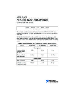
USER GUIDE NI USB-6001/6002/6003
www.ni.comConnector (Micro-B) 80 MHz Clock 5 V Supply Analog Input Analog Output Digital I/O Control Logic 16-Position Screw Termin al Plug I/O Connector AI 7 AO 0 AO 1 AI GND AI 0 AO GND I/O Connector P2.0 PFI 1 PFI 0 5 V D GND P0.0 USB 2.0 Full Speed Interface Counters & PFI

For DM542 - robokits.download
robokits.downloadDM542 Fully Digital Stepper Drive Manual V1.0 3 3. Pin Assignment and Description The DM542 has two connectors, connector P1 for control signals connections, and connector P2 for power and motor