Transcription of 1.0 ACCEPTANCE CRITERIA FOR COMPLETED WELDS
1 LANL Engineering Standards Manual ISD 341-2 Chapter 13, Welding & Joining Section WFP 2-01 Welding Fabrication Procedure Rev. 1, 10/27/06 Attachment 4, ASME , Building Services ACCEPTANCE CRITERIA ACCEPTANCE CRITERIA FOR COMPLETED WELDS butt WELDS No cracks are permitted As-welded surfaces are permitted; however, the surface of WELDS shall be sufficiently free from overlaps, abrupt ridges, and valleys. The thickness of reinforcement shall not exceed 3/16 in. Undercuts shall not exceed 1/32 in. or 12 % of the wall thickness whichever is less. For single-welded joints ( butt joints welded from one side), concavity of the root surface shall not reduce the total thickness of the joint, including reinforcement, to less than the nominal thickness of the thinner component being joined For single welded joints, the excess root penetration shall be exceed the lesser of 1/8 in.
2 Or 5 % of the inside diameter of the pipe. The total joint penetration shall not be less than the thickness of the thinner component being joined, except that incomplete root penetration is acceptable if it does not exceed the lesser of 1/32 in. or 20 % of the required thickness, and its extent is not more than 1 in. in any 6 in. length of weld . Concavity of the root surface shall not be reduced the total thickness of the joint, including reinforcement, to less than the thickness of the thinner of the components being joined. The length of unfused bead or layer areas shall not be more than 20 % of the circumference of the pipe, or of the total length of the weld , and no more than 1 inches in any 6 in.
3 Length of weld . Seal, Socket, and Fillet WELDS As-welded surfaces are permitted; however, the surface of WELDS shall be sufficiently free overlaps, abrupt ridges, and valleys. Limitation on imperfections in socket, fillet and seal WELDS are the same as in Paragraph and for cracks, lack of fusion, and undercut. Socket and fillet WELDS may vary from convex to concave. The size of a fillet weld is determined as shown in page 5. Typical minimum fillet weld details for slip-on flanges and socket-welding components are also shown on page 5. Page 1 of 4 LANL Engineering Standards Manual ISD 341-2 Chapter 13, Welding & Joining Section WFP 2-01 Welding Fabrication Procedure Rev. 1, 10/27/06 Attachment 4, ASME , Building Services ACCEPTANCE CRITERIA FLAT HEAD WELDS AND BRANCH CONNECTIONS ASME Acceptable WELDS for Flat Heads Unacceptable WELDS for Flat Heads Page 2 of 4 LANL Engineering Standards Manual ISD 341-2 Chapter 13, Welding & Joining Section WFP 2-01 Welding Fabrication Procedure Rev.
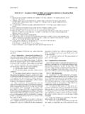
4 1, 10/27/06 Attachment 4, ASME , Building Services ACCEPTANCE CRITERIA Typical weld Branch Connections Typical weld Details Page 3 of 4 LANL Engineering Standards Manual ISD 341-2 Chapter 13, Welding & Joining Section WFP 2-01 Attach Page 4 of 4 Welding Fabrication Procedure Rev. 1, 10/27/06 ment 4, ASME , Building Services ACCEPTANCE CRITERIA FILLET weld PROFILES AND SLIP-ON / SOCKET WELDED FLANGES weld PROFILES Equal Leg Fillet WELDS Surface of Vertical Member The Size of an Equal Leg Fillet weld is the length of the largest inscribed right isosceles triangle. Theoretical Throat = x Size Unequal Leg Fillet For Unequal Leg Fillet WELDS , the Size of the weld is the leg length of the largest right triangle that can be inscribed within the fillet weld cross-section.
5 Slip-on and Socket Welded Flanges x min. = T1 or Thickness of the Hub, whichever is smaller, but not less than 1/8 in. (3 mm) T1 = Minimum Pipe Wall Thickness Theoretical Throat Concave Fillet weld Convex Fillet weld Size of weld Surface of Horizontal Member Theoretical Throat Size of weld Surface of Vertical Member Surface of Horizontal Member Convex Fillet weld Theoretical Throat Concave Fillet weld Theoretical Throat T1 or (6 mm), whichever is Smaller T1x min T1T1x min x min 1/16 ( mm) min. before welding