Transcription of LANL Engineering Standards Manual ISD 341-2 Chapter 13 ...
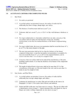
1 LANL Engineering Standards Manual ISD 341-2 Chapter 13, Welding & Joining Section WFP 2-01 Welding Fabrication Procedure Rev. 1, 10/27/06 Attachment 1, ASME , Power Piping Acceptance Criteria ACCEPTANCE CRITERIA FOR COMPLETED WELDS Butt Welds LANL shall have the right to inspect all welds or subject them to mechanical test. Visual examination may be performed during welding or after the welds have been completed. The frequency of visual examinations or other NDE methods shall be as specified in the Engineering procurement or installation specification. As-welded surfaces are permitted; however, the surface of welds shall be sufficiently free from coarse ripples, grooves, overlaps, abrupt ridges, and valleys. The surface condition of the finished welds shall be suitable for the proper interpretation of radiographic and other nondestructive examinations when nondestructive examinations are required.
2 In those cases where there is a question regarding the surface condition on the interpretation of a radiographic film, the film shall be compared to the actual weld surface for interpretation and determination of acceptability. Undercuts shall not exceed 1/32 in. and shall not encroach on the minimum required section thickness. For single-welded joints ( butt joints welded from one side), concavity of the root surface shall not reduce the total thickness of the joint, including reinforcement, to less than the nominal thickness of the thinner component being joined. (This applies only when the inside surface of the weld is readily accessible or the weld has been radiographed.) For single welded joints, the excess root penetration shall be limited to the lesser of 1/8 in. or 25 % of the nominal wall thickness of the thinner component being joined, down to in.
3 Wall thickness. For nominal wall thickness less than in., the excess penetration shall be limited to 1/16 in. (applies only when inside surface of the weld is readily accessible or the weld has been radiographed). weld reinforcement greater than the amounts specified in Figure 1 of this Attachment shall be considered unacceptable. When components of different outside diameters are welded together, the weld joint shall be filled to the outside surface of the component having the larger diameter. There shall be a gradual transition, not exceeding a slope of 1:3, in the weld between the two surfaces. To avoid unnecessary weld deposit, the outside surface of the component having the larger diameter should be tapered at an angle not to exceed 30 with the axis of the pipe (see WFP 2-01, Reference , Figure ). Page 1 of 3 LANL Engineering Standards Manual ISD 341-2 Chapter 13, Welding & Joining Section WFP 2-01 Welding Fabrication Procedure Rev.
4 1, 10/27/06 Attachment 1, ASME , Power Piping Acceptance Criteria Socket and fillet Welds As-welded surfaces are permitted; however, the surface of welds shall be sufficiently free from coarse ripples, grooves, overlaps, abrupt ridges, and valleys. The surface condition of the finished welds shall be suitable for the proper interpretation of nondestructive examinations, where required. Socket and fillet welds may vary from convex to concave. The size of a fillet weld is determined as shown in Figure 2 of this Attachment. Typical minimum fillet weld details for slip-on flanges and socket-welding components are also contained in Figure 2 of this Attachment. Undercuts shall not exceed 1/32 in. and shall not encroach on the minimum required section thickness. Figure 1 weld REINFORCEMENT TABLE ASME Thickness of Thickness of Reinforcement for Design Temperature Base Material Greater than 750 F (400 C) 350 F to 750 F (175 C to 400 C) Less than 350 F (175 C) Up to 1/8 in.
5 (3 mm), inclusive 1/16 in. ( mm) 3/32 in. (2 mm) 3/16 in. (5 mm) Over 1/8 in. to 3/16 in. (3 mm to 5 mm) 1/16 in. ( mm) 1/8 in. (3 mm) 3/16 in. (5 mm) Over 3/16 in. to in. (5 mm to 13 mm) 1/16 in. ( mm) 5/32 in. (4 mm) 3/16 in. (5 mm) Over in. to 1 in. (13 mm to 25 mm) 3/32 in. (2 mm) 3/16 in. (5 mm) 3/16 in. (5 mm) Over 1 in. to 2 in. (25 mm to 50 mm) 1/8 in. (3 mm) in. (6 mm) in. (6 mm) Over 2 in. (50 mm) 5/32 in. (4 mm) greater of in. (6 mm) or 1/8 x width of the weld NOTES: 1. For double welded butt joints, the allowable reinforcement shall apply separately to both inside and outside surfaces of the joint. 2. For single welded butt joints, the allowable reinforcement shall apply to the outside surface of the joint only. 3. The thickness of weld reinforcement shall be based on the thickness of the thinner component being joined. 4. The weld reinforcement thickness shall be determined from the higher of the abutting surfaces involved. 5. weld reinforcement may be removed if desired.
6 6. Undercuts shall not exceed 1/32 in. (1 mm) at the toe of either leg of the fillet weld . Page 2 of 3 LANL Engineering Standards Manual ISD 341-2 Chapter 13, Welding & Joining Section WFP 2-01 Welding Fabrication Procedure Rev. 1, 10/27/06 Attachment 1, ASME , Power Piping Acceptance Criteria Figure 2 fillet weld PROFILES AND SLIP-ON / SOCKET WELDED FLANGES weld PROFILES Equal Leg fillet Welds Surface of Vertical Member The size of an Equal Leg fillet weld is the length of the largest inscribed right isosceles triangle. Theoretical Throat = x size Unequal Leg fillet Welds For Unequal Leg fillet Welds, the size of the weld is the leg length of the largest right triangle that can be inscribed within the fillet weld cross-section. Slip-on and Socket Welded Flanges x min. = T1 or Thickness of the Hub, whichever is smaller, but not less than 1/8 in. (3 mm) T1 = minimum Pipe Wall Thickness Theoretical Throat Concave fillet weld Convex fillet weld size of weld Surface of Horizontal Member Theoretical Throat size of weld Surface of Vertical Member Surface of Horizontal Member Convex fillet weld Theoretical Throat Concave fillet weld Theoretical Throat T1 or (6 mm), whichever is Smaller T1x min T1T1x min x min 1/16 ( mm) min.
7 Before welding Page 3 of 3