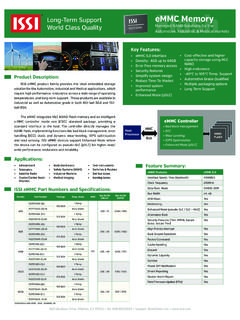
Transcription of 1.2W AUDIO POWER AMPLIFIER WITH ACTIVE-LOW …
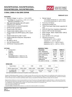
1 IS31AP4991. AUDIO POWER AMPLIFIER with ACTIVE-LOW standby MODE. October 2012. GENERAL DESCRIPTION FEATURES. The IS31AP4991 has been designed for demanding Operating from VCC = ~ AUDIO applications such as mobile phones and permits output POWER @ VCC = 5V, THD+N= 1%, the reduction of the number of external components. f = 1kHz, with 8 load It is capable of delivering of continuous RMS Ultra-low consumption in standby mode (much output POWER into an 8 load @ 5V. less than 1 A). An externally-controlled standby mode reduces the 65dB PSRR @217Hz in grounded mode supply current to much less than 1 A. It also includes Near-zero click-and-pop internal thermal shutdown protection. Ultra-low distortion 1kHz). SOP-8 and MSOP-8 package The unity-gain stable AMPLIFIER can be configured by external gain setting resistors.
2 APPLICATIONS. Mobile phones PDAs Portable electronic devices Notebook computer TYPICAL APPLICATION CIRCUIT. Figure 1 Typical Application Circuit (Single-ended input). Integrated Silicon Solution, Inc. 1. Rev. B, 10/18/2012. IS31AP4991. Figure 2 Typical Application Circuit (Differential input). Integrated Silicon Solution, Inc. 2. Rev. B, 10/18/2012. IS31AP4991. PIN CONFIGURATION. Package Pin Configuration (Top View). SOP-8. MSOP-8. PIN DESCRIPTION. No. Pin Description SOP MSOP. IN+ 1 3 Positive input of the first AMPLIFIER . Negative output of the IS31AP4991. Connected to the OUT- 2 5. load and to the feedback resistor RF. Negative input of the first AMPLIFIER , receives the AUDIO IN- 3 4 input signal. Connected to the feedback resistor RF. and to the input resistor RIN. GND 4 7 Ground. Bypass capacitor pin which provides the common BYPASS 5 2.
3 Mode voltage (VCC/2). Positive output of the IS31AP4991. Connected to the OUT+ 6 8. load. The device enters shutdown mode when a low level is SDB 7 1. applied on this pin. VCC 8 6 Positive analog supply of the chip. Integrated Silicon Solution, Inc. 3. Rev. B, 10/18/2012. IS31AP4991. ORDERING INFORMATION. Industrial Range: -40 C to +85 C. Order Part No. Package QTY/Reel IS31AP4991-GRLS2-TR SOP-8, Lead-free 2500. IS31AP4991-SLS2-TR MSOP-8, Lead-free 2500. Copyright 2012 Integrated Silicon Solution, Inc. All rights reserved. ISSI reserves the right to make changes to this specification and its products at any time without notice. ISSI assumes no liability arising out of the application or use of any information, products or services described herein. Customers are advised to obtain the latest version of this device specification before relying on any published information and before placing orders for products.
4 Integrated Silicon Solution, Inc. does not recommend the use of any of its products in life support applications where the failure or malfunction of the product can reasonably be expected to cause failure of the life support system or to significantly affect its safety or effectiveness. Products are not authorized for use in such applications unless Integrated Silicon Solution, Inc. receives written assurance to its satisfaction, that: a.) the risk of injury or damage has been minimized; b.) the user assume all such risks; and c.) potential liability of Integrated Silicon Solution, Inc is adequately protected under the circumstances Integrated Silicon Solution, Inc. 4. Rev. B, 10/18/2012. IS31AP4991. ABSOLUTE MAXIMUM RATINGS (Note 1). Supply voltage, VCC ~ + Voltage at any input pin ~ VCC+ Maximum junction temperature, TJMAX 150 C.
5 Storage temperature range, TSTG -65 C ~ +150 C. Operating temperature range, TA 40 C ~ +85 C. Note 1: Stresses beyond those listed under Absolute Maximum Ratings may cause permanent damage to the device. These are stress ratings only and functional operation of the device at these or any other condition beyond those indicated in the operational sections of the specifications is not implied. Exposure to absolute maximum rating conditions for extended periods may affect device reliability. ELECTRICAL CHARACTERISTICS. The following specifications apply for CIN = F, RIN = RF = 20k , CBYPASS = 1 F, unless otherwise specified. Limits apply for TA = 25 C. VCC=5V (Note 2 or specified). Symbol Parameter Condition Typ. Limit Unit ICC Quiescent POWER supply current VCC = 0V, Io = 0A, no Load mA (max). ISTBY standby current VSTBY = GND, RL = 1 A(max).
6 VSTBYH Shutdown voltage input high VCC = V(min). VSTBYL Shutdown voltage input low VCC = V(max). VOS Output offset voltage 15 mV (max). THD+N = 1%; f = 1kHz Po Output POWER (8 ) W. THD+N = 10%; f = 1kHz tWU Wake-up time (Note 3) CBYPASS = 1 F 115 ms Total harmonic distortion+noise THD+N Po = ; f = 1kHz %. (Note 3). POWER supply rejection ratio Vripple p-p = 200mV f = 217Hz 65. PSRR dB. (Note 3) Input Grounded f = 1kHz 77. The following specifications apply for CIN = F, RIN = RF = 20k , CBYPASS = 1 F, unless otherwise specified. Limits apply for TA= 25 C. VCC=3V (Note 2 or specified). Symbol Parameter Condition Typ. Limit Unit ICC Quiescent POWER supply current VCC = 0V, Io = 0A, no Load mA(max). ISTBY standby current VSTBY = GND, RL = 1 A(max). THD+N = 1%; f = 1kHz 405. Po Output POWER (8 ) mW. THD+N = 10%; f = 1kHz 502.
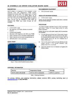
7 TWU Wake-up time (Note 3) CBYPASS = 1 F 102 ms Total harmonic distortion+noise THD+N Po = ; f = 1kHz %. (Note 3). Note 2: Production testing of the device is performed at 25 C. Functional operation of the device and parameters specified over other temperature range, are guaranteed by design, characterization and process control. Note 3: Guaranteed by design. Integrated Silicon Solution, Inc. 5. Rev. B, 10/18/2012. IS31AP4991. TYPICAL PERFORMANCE CHARACTERISTIC. 10 10. Vcc = 3V Vcc = 5V. 5 RL = 8 5 RL = 8 . 2 f = 1kHz 2 f = 1kHz 1 1. THD+N (%). THD+N (%). 10m 20m 50m 100m 200m 500m 1 2 10m 20m 50m 100m 200m 500m 1 2. Output POWER (W) Output POWER (W). Figure 3 THD+N vs. Output POWER Figure 4 THD+N vs. Output POWER 10 10. 5 Vcc = 3V 5 Vcc = 5V. RL = 8 RL = 8 . 2 POWER =250mW POWER =800mW. 2. 1 1. THD+N (%). THD+N (%).
8 0 .05. 0 .02. 0 .01. 20 50 100 200 500 1k 2k 5k 20k 20 50 100 200 500 1k 2k 5k 20k Frequency (Hz) Frequency (H z). Figure 5 THD+N vs. Frequency Figure 6 THD+N vs. Frequency Figure 7 PSRR vs. Frequency Figure 8 PSRR vs. Frequency Integrated Silicon Solution, Inc. 6. Rev. B, 10/18/2012. IS31AP4991. 100 u Vcc = 5V. 70 u RL = 8 . PoWeighted A = 800mWFilter Output Noise Voltage (V). 50 u 40 u 30 u 20 u 10 u 20 50 100 200 500 1k 2k 5k 20k Frequency (Hz). Figure 9 Noise Floor Figure 10 Output POWER vs. POWER Supply Integrated Silicon Solution, Inc. 7. Rev. B, 10/18/2012. IS31AP4991. APPLICATION INFORMATION. BTL CONFIGURATION PRINCIPLE fCH is in Hz. The IS31AP4991 is a monolithic POWER AMPLIFIER with a 1. BTL output type. BTL (bridge tied load) means that f CH . each end of the load is connected to two single-ended 2 RF C F.
9 Output amplifiers. Thus, we have: DECOUPLING OF THE CIRCUIT. Single-ended output 1 = VOUT+ = VOUT (V). Two capacitors are needed to correctly bypass the Single ended output 2 = VOUT- = -VOUT (V) IS31AP4991: a POWER supply bypass capacitor CS and a bias voltage bypass capacitor CBYPASS. and CS has particular influence on the THD+N in the high VOUT+ - VOUT- = 2 VOUT (V) frequency region (above 7kHz) and an indirect The output POWER is: influence on POWER supply disturbances. with a value for CS of 1 F, you can expect THD+N levels similar to (2 VOUT RMS ) 2 those shown in the datasheet. POUT . RL In the high frequency region, if CS is lower than 1 F, it increases THD+N and disturbances on the POWER For the same POWER supply voltage, the output POWER supply rail are less filtered. in BTL configuration is four times higher than the output POWER in single ended configuration.
10 On the other hand, if CS is higher than 1 F, those disturbances on the POWER supply rail are more filtered. GAIN IN A TYPICAL APPLICATION SCHEMATIC. CBYPASS has an influence on THD+N at lower The typical application schematic is shown in Figure 1 frequencies, but its function is critical to the final result on page 1. of PSRR ( with input grounded and in the lower In the flat region (no CIN effect), the output voltage of frequency region). the first stage is (in Volts): If CBYPASS is lower than 1 F, THD+N increases at lower frequencies and PSRR worsens. RF. VOUT ( VIN ) If CBYPASS is higher than 1 F, the benefit on THD+N at RIN lower frequencies is small, but the benefit to PSRR is For the second stage: VOUT+ = -VOUT- (V) substantial. The differential output voltage is (in Volts): Note that CIN has a non-negligible effect on PSRR at lower frequencies.