Transcription of 1 (32mm) DIAMETER B-5898 STAINLESS STEEL Technical …
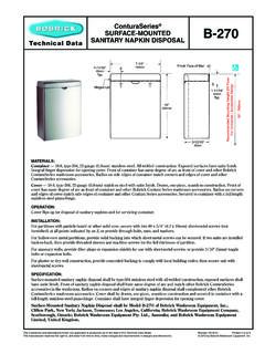
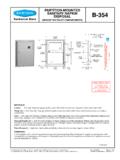
1 11/4" (32mm) DIAMETER . STAINLESS STEEL B-5898 . Technical Data 30" x 30" (762 x 762mm). 90-DEGREE GRAB BAR. Specify Finish Required: Satin finish Satin finish with peened gripping surface; add suffix .99 to model number 30''. 760mm 30''. 760mm MATERIALS: Grab Bar 18-8, type-304, 18-gauge ( ) STAINLESS STEEL tubing with satin-finish. 1-1/4" (32mm) outside DIAMETER . Ends are heliarc welded to concealed mounting flanges. Clearance between the grab bar and wall is 1-1/2" (38mm). Concealed Mounting Flanges 18-8, type-304, 1/8" (3mm) thick, STAINLESS STEEL plate; end flanges 2" x 3-1/8" (50 x 80mm) with two holes for attachment to wall. Intermediate flanges 2-5/8" x 3-1/8" (65 x 80mm) wide x 3-1/8" (80mm) DIAMETER . Snap Flange Covers 18-8, type-304, 22-gauge ( ) drawn STAINLESS STEEL with satin-finish. 3-1/4" (85mm) DIAMETER x 5/8" (16mm) deep. Each cover snaps over mounting flange to conceal mounting screws.
2 STRENGTH: Bobrick grab bars that provide 1-1/2" (38mm) clearance from wall can support loads in excess of 900 pounds (408kg) if properly installed. Other grab bar configurations can support loads in excess of 250 pounds (113kg) if properly installed, complying with accessible design (including ADAAG in the ) for structural strength. Safety Warning: Grab bars are no stronger than the anchors and walls to which they are attached and, therefore, must be firmly secured in order to support the loads for which they are intended. To avoid potential injur y, the building owner or maintenance personnel should remove the grab bar from ser vice if the grab bar is not adequately secured to wall or if there is any obser ved damage to the welds. continued .. The illustrations and descriptions herein are applicable to production as of the date of this Technical Data Sheet.
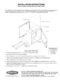
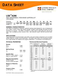
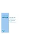
3 Rev. 11/23/15 Printed in The manufacturer reserves the right to, and does from time to time, make changes and improvements in designs and dimensions. 2015 by Bobrick Washroom Equipment, Inc. INSTALLATION: Provide concealed anchor device or backing as specified or required in accordance with local building codes before wall is finished. Fasten concealed mounting flanges to anchor device or backing with two screws in each flange. Snap flange covers over each mounting flange to conceal mounting screws. Concealed anchor devices and mounting screws are not included with Bobrick grab bars and must be specified as an accessory. For Grab Bars with an Intermediate Flange(s), Pull Snap-Flange Covers away from mounting flanges. Place grab bar in desired mounting location. Use intermediate flange as a template to mark location of mounting screws at intermediate flange only.
4 Mark screw locations at the center of the slot in the middle of the double-keyhole shaped mounting holes (2) in the intermediate flange. Remove grab bar from wall. Drive the intermediate flange mounting screws into wall at marked locations. Note: Make sure to leave a space of just over 1/8'' ( ) between the underside of the screw head and the wall. Install grab bar on the wall by placing the round ends of the intermediate flange double-keyhole shaped mounting holes over the mounting screws (2) are located in the middle of the flange slots. Install the mounting screws into the wall at the end flanges and secure tightly. Tighten the mounting screws at the intermediate flange. Press all snap-flange covers into place to conceal mounting flanges. Note: Recommend use of 1/4'' or #14 sheet metal or wood screws to install Intermediate Flange. #12 screws may also be used.
5 Important Notes: 1. Mounting Kits Bobrick offers a mounting kit for installing grab bars; one Bobrick mounting kit is required for each flange. Mounting Kit No. Description 252-30 Consists of #14 x 2 '' type-304 STAINLESS STEEL , Phillips round-head, sheet-metal screws. 2. Grab Bar Fastener Bobrick offers a grab bar fastening system that secures all Bobrick grab bar series; one Bobrick fastener is required for each flange. Install grab bar without backing in wall requires minimum 5/8" (16mm) thick painted or tiled drywall. WingIt Fastener No. Description 251-4 Consists of 10 32 x 5/16'' round-head, Phillips 18/8 STAINLESS STEEL screws. (1) WingIt grab bar fastener. Optional Anchor Device Bobrick grab bar anchor device includes STAINLESS STEEL machine screws to be used for attaching grab bars to anchors. 3. one Bobrick concealed anchor device is required for each flange.
6 Optional Anchor No. Description 2583 Anchor for 3/4" to 1" (19-25mm) panel 1 anchor required for each flange. 2586 Anchor for 1/2" to 1" (13mm) panel 1 anchor required for each flange. SPECIFICATION: Grab bar shall be type-304 STAINLESS STEEL with satin-finish. Grab bar shall have 18-gauge ( ) wall thickness and 1-1/4" (32mm) outside DIAMETER . Clearance between the grab bar and wall shall be 1-1/2" (38mm). Concealed mounting flanges shall be 1/8" (3mm) thick STAINLESS STEEL plate, 2" x 3 1/8" (50 x 80mm), and equipped with two screw holes for attachment to wall. Flange covers shall be 22-gauge ( ) STAINLESS STEEL , 3-1/4" (85mm) DIAMETER , and shall snap over mounting flanges to conceal mounting screws and/or WingIt fasteners. Ends of grab bar shall pass through concealed mounting flanges and be heliarc welded to form one structural unit. Grab bar shall comply with accessible design (including ADAAG in the ) for structural strength.
7 Grab Bar shall be Model _____ (insert model number) of Bobrick Washroom Equipment, Inc., Clifton Park, New York; Jackson, Tennessee; and Los Angeles, California; Bobrick Washroom Equipment Company, Scarborough, Ontario; Bobrick Washroom Equipment Pty. Ltd., Australia; and Bobrick Washroom Equipment Limited, United Kingdom. The illustrations and descriptions herein are applicable to production as of the date of this Technical Data Sheet. B-5898 -200 11/23/15 Printed in The manufacturer reserves the right to, and does from time to time, make changes and improvements in designs and dimensions. 2015 by Bobrick Washroom Equipment, Inc.