Transcription of 1. Design a Gray Code to BCD converter by the following ...
1 DEPARTMENT OF MECHANICAL & aerospace ENGINEERING UNIVERSITY AT BUFFALO MAE 476/576 Mechatronics Spring 2003 Mini Assignment 4 Solution 1. Design a Gray Code to BCD converter by the following procedures: a. Write down the truth table of the converter . Binary Coded Decimal (BCD) is a way to store the decimal numbers in binary form. The number representation requires 4 bits to store every decimal digit (from 0 to 9). Since there are 10 different combinations of BCD, we need at least a 4-bit Gray Code to create sufficient number of these combinations. The truth table is: Gray Code BCD Decimal A B C D W X Y Z 0 0 0 0 0 0 0 0 0 1 0 0 0 1 0 0 0 1 2 0 0 1 1 0 0 1 0 3 0 0 1 0 0 0 1 1 4 0 1 1 0 0 1 0 0 5 0 1 1 1 0 1
2 0 1 6 0 1 0 1 0 1 1 0 7 0 1 0 0 0 1 1 1 8 1 1 0 0 1 0 0 0 9 1 1 0 1 1 0 0 1 10 1 1 1 1 D D D D 11 1 1 1 0 D D D D 12 1 0 1 0 D D D D 13 1 0 1 1 D D D D 14 1 0 0 1 D D D D 15 1 0 0 0 D D D D b. Apply Karnaugh Map to look for the minimized logic expression. Karnaugh Map for W: Minimal Expression for W: W = A Karnaugh Map for X: Minimal Expression for X: X = A B 0001111000001D01001D1100DD1000 DDADCB0001111000010D01010D1101DD1001 DDADCBK arnaugh Map for Y: Y = A BC + B C Karnaugh Map for Z: Z = A BC D + B C D + AD + BCD + B CD 0001111000010D01010D1110DD1010 DDADCB0001111000010D01101D1101DD1010 DDADCB c.
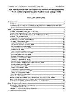
3 Implement the logic gates by using Circuit Maker.