Transcription of 17 BEAMS SUBJECTED TO TORSION AND BENDING -I
1 BEAMS SUBJECTED TO BENDING AND TORSION -I 17 BEAMS SUBJECTED TO TORSION AND BENDING -I INTRODUCTION When a beam is transversely loaded in such a manner that the resultant force passes through the longitudinal shear centre axis, the beam only bends and no TORSION will occur. When the resultant acts away from the shear centre axis, then the beam will not only bend but also twist. When a beam is SUBJECTED to a pure BENDING moment, originally plane transverse sections before the load was applied, remain plane after the member is loaded.
2 Even in the presence of shear, the modification of stress distribution in most practical cases is very small so that the Engineer s Theory of BENDING is sufficiently accurate. If a beam is SUBJECTED to a twisting moment, the assumption of planarity is simply incorrect except for solid circular sections and for hollow circular sections with constant thickness. Any other section will warp when twisted. Computation of stress distribution based on the assumption of planarity will give misleading results.
3 Torsional stiffness is also seriously affected by this warping. If originally plane sections remained plane after twist, the torsional rigidity could be calculated simply as the product of the polar moment of inertia (Ip = Ixx + Iyy) multiplied by (G), the shear modulus, viz. G. (Ixx + Iyy). Here Ixx and Iyy are the moments of inertia about the principal axes. This result is accurate for the circular sections referred above. For all other cases, this is an overestimate; in many structural sections of quite normal proportions, the true value of torsional stiffness as determined by experiments is only 1% - 2% of the value calculated from polar moment of inertia.
4 It should be emphasised that the end sections of a member SUBJECTED to warping may be modified by constraints. If the central section remains plane, for example, due to symmetry of design and loading, the stresses at this section will differ from those based on free warping. Extreme caution is warranted in analysing sections SUBJECTED to TORSION . UNIFORM AND NON-UNIFORM TORSION Shear Centre and Warping Shear Centre is defined as the point in the cross-section through which the lateral (or transverse) loads must pass to produce BENDING without twisting.
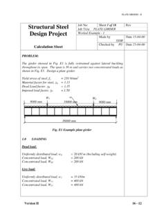
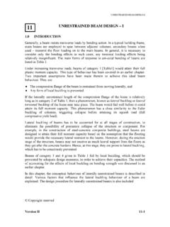
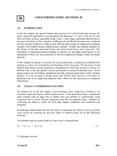
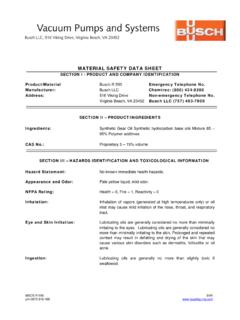
5 It is also the centre of rotation, when only pure torque is applied. The shear centre and the centroid of the cross section will coincide, when section has two axes of symmetry. The shear centre will be on the axis of symmetry, when the cross section has one axis of symmetry. Copyright reserved Version II 17-1 BEAMS SUBJECTED TO BENDING AND TORSION -I Table 1: Properties of Sections twh/2 h b o )2(324:3233233hbtJbhtCtttIfhtbtJfwwfwf+= ===+=tf ()323132312213332132313112)(33:bbbbhtChb btJhttbbJtttIfbbbhefwwfwf+=++=++===+=hbh bhtbCbhthbhbthbtJhbhbCtttIfhtbtJwwfwwfwf ++=+++ +=+===+=2212]3)(2[)2(3)2(12:322322322333 hbhbhtbChtbthtbthbtChbtJhtbtJhbtbetttIfh tbttbewwfwffwwwfwfwff++=++=+=+=+===+=623 1262312)2(33263.
6 63232333322 = ====== = cossin)cos( :2cossincossin223535533tataCtaCatJaetaJI faewwo t a e o b2b1twe h tfb h e twtfb tftwo h/2 h b b Version II 17-2 BEAMS SUBJECTED TO BENDING AND TORSION -I where O = shear centre; J = TORSION constant; Cw = warping constant If the loads are applied away from the shear centre axis, TORSION besides flexure will be the evident result. The beam will be SUBJECTED to stresses due to TORSION , as well as due to BENDING . The effect of torsional loading can be further split into two parts, the first part causing twist and the second, warping.
7 These are discussed in detail in the next section. Warping of the section does not allow a plane section to remain as plane after twisting. This phenomenon is predominant in Thin Walled Sections, although consideration will have to be given to warping occasionally in hot rolled sections. An added characteristic associated with TORSION of non-circular sections is the in-plane distortion of the cross-section, which can usually be prevented by the provision of a stiff diaphragm. Distortion as a phenomenon is not covered herein, as it is beyond the scope of this chapter.
8 Methods of calculating the position of the shear centre of a cross section are found in standard textbooks on Strength of Materials. Classification of TORSION as Uniform and Non-uniform As explained above when TORSION is applied to a structural member, its cross section may warp in addition to twisting. If the member is allowed to warp freely, then the applied torque is resisted entirely by torsional shear stresses (called St. Venant's torsional shear stress). If the member is not allowed to warp freely, the applied torque is resisted by St.
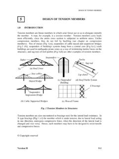
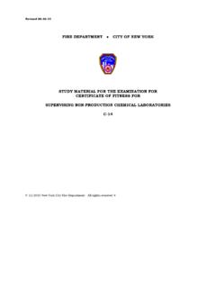
9 Venant's torsional shear stress and warping TORSION . This behaviour is called non-uniform TORSION . Hence (as stated above), the effect of TORSION can be further split into two parts: Uniform or Pure TORSION (called St. Venant's TORSION ) - Tsv Non-Uniform TORSION , consisting of 's TORSION (Tsv) and warping TORSION (Tw). Uniform TORSION in a Circular Cross Section Let us consider a bar of constant circular cross section SUBJECTED to TORSION as shown in Fig. 1. In this case, plane cross sections normal to the axis of the member remain plane after twisting, there is no warping.
10 The torque is solely resisted by circumferential shear stresses caused by St. Venant's TORSION . Its magnitude varies as its distance from the centroid. For a circular section, the St. Venant's TORSION is given by )1(dzdGI Tpsv =Version II 17-3 BEAMS SUBJECTED TO BENDING AND TORSION -I where, - angle of twist G - modulus of rigidity Tsv - St. Venant's TORSION . Ip - the polar moment of inertia z - direction along axis of the member. T T Z Fig.