Transcription of 1CT0302 / 1CT0303 CONCENTRIC VENT TERMINATION
1 1CT0302 / 1CT0303 CONCENTRIC VENT TERMINATION FOR USE WITH ALL CONDENSING GAS FURNACE MODELSACCESSORY KIT INSTALLATION INSTRUCTIONS035-14287-000 / 66641-UIM-F-0905 Unitary Products GroupGENERALThis accessory allows both the intake for combustion air andthe exhaust vent to pass through a common roof or sidewallpenetration. This TERMINATION is available as an option to thestandard two pipe intake/vent shown in the basic furnaceinstallation this instruction for installation of the CONCENTRIC termi-nation kit. Follow the basic furnace installation instruction forinstallation of the intake/vent pipe(s) and all furnace installa-tion CONCENTRIC intake/vent TERMINATION accessories are avail-able.
2 1CT0302 is for use with 2" intake/vent is for use with 3" intake/vent to the furnace installation instructions for intake/vent pipe sizing : This CONCENTRIC TERMINATION accessory reduces theallowable intake/vent piping length by 5 feet from that listed inthe basic furnace installation kit contains the following parts:(1) Combustion Air Inlet Cap(1) Air Inlet Pipe(1) Vent Pipe (1) Intake/Vent CONCENTRIC Y (1) Installation Instruction (035-14287-000)Field supplied pipe and fittings are required to completeinstallation. The combustion air and vent pipe fittings mustconform to American National Standards Institute (ANSI) andAmerican Society for Testing and Materials (ASTM) stan-dards D1785 (Schedule 40 PVC), F891 (PVC--DWV cellularcore), D2665 (PVC--DWV), D2241 (SDR--26 PVC), D2661(ABS--DWV), or F628 (Schedule 40 ABS).
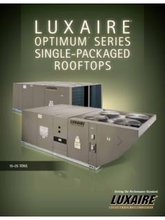
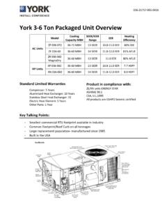
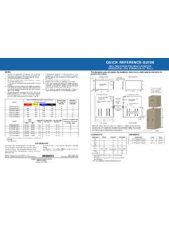
3 Pipe cement andprimer must conform to ASTM standards D2564 (PVC) orD2235 (ABS).In Canada, construct all combustion air and vent pipes forthis unit of CSA or ULC certified Schedule 40 PVC, PVC-DWV, or ABS-DWV pipe and pipe accessory must be used only for terminatingthe vent of a Category IV furnace. Do not use thistermination kit for any other type furnace. Failure tofollow this warning could result in fire, personalinjury or not operate the furnace until the installation andassembly of this intake/vent terminal and all pipingare completed. Failure to follow this warning couldresult in product damage or improper operation,personal injury or 1 - Vent Terminal AssemblyMODELINTAKE/VENT NOM.
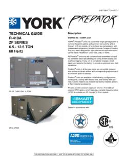
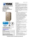
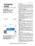
4 PIPE SIZEOVERALL ASSEM D LENGTH11. This is the dimension as shipped. This may be field modified by cutting or extending both the intake and exhaust pipes. 12" is the minimum allowable length and 60" is the maximum allow-able length for this dimension. SDR-26 PVC (D2241) only may be used for extending pipes. Do not use Schedule 40 PVC or use couplings to extend PIPE OUTSIDEDIAMETERAIR INLETPIPE LENGTH22. This dimension will change if the intake/vent pipes are length-ened or 2" 34-3/4" 3-1/2" 27-1/4" 1CT0303 3" 39-3/4 4-1/2" 31-7/8" FIGURE 2 - Typical Roof InstallationASSEMBLED TERMINAL3 OR 4 DIAMETERAIR INLET PIPE2 OR 2-1/2 DIAMETERVENT PIPE Y CONCENTRIC FITTINGCOMBUSTIONAIR INLET CAP\VENTCOMBUSTION AIRMAINTAIN 12 MINIMUM (18 for Canada)MINIMUM CLEARANCEABOVE HIGHESTANTICIPATED SNOW LEVELMAXIMUM OF 24 ABOVEROOF035-14287-000 / 66641-UIM-F-09052 Unitary Products GroupVERTICAL ROOF MOUNTINGNOTE.
5 Roof mounting is the recommended intake/vent loca-tion. This allows less intake air contaminants and alsoreduces complaints caused by exhaust vapors near pipe diameter from furnace correct CONCENTRIC vent TERMINATION accessoryfor the pipe diameter the best location for the a 4" diameter hole for 1CT0302 , 2" kit, or a 5" holefor 1CT0303 , 3" assemble CONCENTRIC vent TERMINATION kit. Cleanand cement using procedures explained in the furnaceinstallation Y CONCENTRIC fitting to larger diameter airinlet pipe (refer to Figure 1). combustion air inlet cap to smaller diameterpipe (refer to Figure 1). Y CONCENTRIC fitting and pipe assembly throughthe structure's hole and field supplied roof : Do not allow insulation to accumulate inside assem-bly when installing through : Multiple CONCENTRIC vent kits may be installed for ver-tical application following the same clearances between ventoutlets as shown in Figure assembly to roof structure as shown in Figure 3using field supplied metal strapping or equivalentsupport : Ensure TERMINATION height is above roof surface oranticipated snow level (minimum 12.)
6 In or minimum 18 .in Canada) as shown in Figures 2 & : If assembly is too short to meet height requirement,the 2 pipes supplied in the kit may be replaced by using samediameter, field supplied SDR--26 PVC (D2241) pipe. Do notuse Schedule 40 PVC or couplings to extend pipes. The addi-tional wall thickness will restrict combustion air and maycause operational problems. Do not extend air inlet pipemore than 60" (refer to Figure 3). combustion air inlet cap and small diameter pipeassembly into roof penetration. Make sure smalldiameter pipe is cemented and bottomed in Y CONCENTRIC furnace combustion air and vent pipes toconcentric vent TERMINATION assembly.
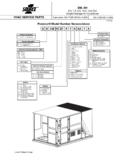
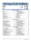
7 Refer to Figure 3for proper pipe Operate furnace through one heat cycle to verify propersystem SIDEWALL MOUNTINGNOTE: In all horizontal intake/vent applications the followingitems should be considered before a final location is deter-mined. Refer to 2-pipe vent clearances in the furnace installation instructions to determine allowable locations and required clearances. If venting multiple units using multiple CONCENTRIC vents , refer to Figures 4 & 6 for specific clearances. Do not locate this TERMINATION where it is subjected to prevailing winds. Do not locate this TERMINATION where it is likely to receive physical damage. Do not locate this TERMINATION where vent vapors are objectionable, or may damage the structure, plants or air conditioning condensing 3 - Typical Roof InstallMAINTAIN 12 (18 for Canada)MINIMUM CLEARANCE ABOVEHIGHEST ANTICIPATED SNOWLEVEL.
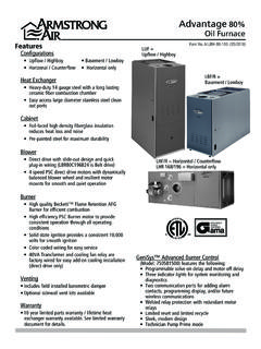
8 MAXIMUM OF 24 ABOVE AIRROOF WEATHERSEAL/FLASHING(field supplied)SUPPORT(field supplied)ELBOW(field supplied)COMBUSTION Do not use field supplied couplings to extend / 66641-UIM-F-0905 Unitary Products Group3 FIGURE 4 - Sidewall TERMINATION for Multiple Vertical CONCENTRIC VentFIGURE 5 - Sidewall TERMINATION for CONCENTRIC VentROOF OVERHANG12 MINIMUM36 MINIMUMVENT1 COMBUSTION AIRMAINTAIN 12 CLEARANCEABOVE HIGHEST ANTICIPATEDSNOW LEVEL OR GRADEROOFOVERHANG12 MINIMUMVENT1 COMBUSTION AIRMAINTAIN 12 CLEARANCEABOVE HIGHEST ANTICIPATEDSNOW LEVEL OR GRADEFIGURE 6 - Sidewall TERMINATION for Multiple Horizontal CONCENTRIC VentFIGURE 7 - Sidewall TERMINATION Details for CONCENTRIC Vent4 MAXIMUM OR 24 MINIMUM(Between end Bell Edges)
9 ROOFOVERHANG12 MINIMUM1 VENTCOMBUSTION AIRMAINTAIN 12 CLEARANCEABOVE HIGHEST ANTICIPATEDSNOW LEVEL OR COMBUSTIONAIR INLETVANES TOWALLELBOW(field supplied)COMBUSTIONAIRSTRAP(field supplied)NOTE:SECURING STRAP MUST BE FIELDINSTALLED TO PREVENT MOVEMENTTO TERMINATION KIT IN SIDE Subject to change without notice. Printed in / 66641-UIM-F-0905 Copyright by York International Corp. 2005. All rights : 66641-UIM-E-1004 / 035-14287-000 Rev. E (1004)Unitary5005 pipe diameter from furnace correct CONCENTRIC vent TERMINATION accessoryfor the pipe diameter the best location for the installing multiple CONCENTRIC vents .
10 The followingguidelines should be CONCENTRIC vents should not be installeddirectly above one another unless separated by aminimum distance of 3 CONCENTRIC vents should be installed wherethe horizontal distance between the end bells ofeach air intake is 4" or less or greater than 24" toprevent a recirculation of flue gas from one vent tothe adjacent air a 4" diameter hole for 1CT0302 , 2" kit, or a 5" holefor 1CT0303 , 3" assemble CONCENTRIC vent TERMINATION kit. Cleanand cement using procedures explained in the furnaceinstallation Y CONCENTRIC fitting to larger diameter airinlet pipe (refer to Figure 1).