Transcription of 2/2, 3/2 and 4/2 directional seat Replaces: 07.06 …
1 1/14 Information on available spare parts: , 3/2 and 4/2 directional seat valve with solenoid actuationType 6 Component series 1 XMaximum operating pressure 350 bar [5100 psi]Maximum flow 25 l/min [ gpm]RE 22049 : of contentsFeatures Direct operated directional seat valve with solenoid actuation Porting pattern according to DIN 24340 form A (without locating hole) Porting pattern according to ISO 4401-03-02-0-05 and NFPA R2-2002 D03 (with locating hole) Safe switching also with longer standstill periods under pressure Wet-pin DC voltage solenoids with detachable coil (AC volt-age possible by means of a rectifier) solenoid coil can be rotated by 90 The coil can be changed without having to open the pres-sure-tight chamber Electrical connection as individual connection (for more elec-trical connections, see RE 08010)
2 With concealed manual override, optional Inductive position switch (contactless), see RE 24830H4243 Contents PageFeatures 1 Ordering code 2, 3 Function, section, symbols 4, 5 Technical data 6 Characteristic curves 7 Performance limit 8 Unit dimensions 9 to 12 Valve mounting screws 13 Mating connectors 13 Throttle insert 14 Check valve insert 14 General notes 14 InhaltTable of contents 1 Features 1 Ordering code 2 3 Function, section, symbols: 2/2 and 3/2 directional seat valve 4 Function, section, symbols, schematic illustration: 4/2 direc - tional seat valve 5 Technical data (For applications outside these parameters, please consult us!) 6 Characteristic curves (measured with HLP46, Oil = 40 5 C [104 9 F]) 7 Performance limit (measured with HLP46, Oil = 40 5 C [104 9 F]) 8 Unit dimensions: 2/2 directional seat valve ( PK ) and 3/2 way seat valve ( UK )(dimensions in mm [inch]) 9 Unit dimensions: 2/2 directional seat valve ( NK ) and 3/2 directional seat valve ( CK )(dimensions in mm [inch]) 10 Unit dimensions: 4/2 directional seat valve ( D ) (dimensions in mm [inch]) 11 Unit dimensions.
3 4/2 directional seat valve ( Y ) (dimensions in mm [inch]) 12 Valve mounting screws 13 Mating connectors according to DIN EN 175301-803 13 Throttle insert 14 General notes 14 Check valve insert 14 Notes 15 Notes 162/14 Bosch Rexroth AG RE 22049 code2 main ports = 23 main ports = 34 main ports = 4 Seat valveSize 6 = 6 Main ports234 SymbolsAPaabb = PKAP aabb = NKAPT aabb = UKAPT aabb = CKabABPTab = DabABPTab = Y = AvailableComponent series 10 to 19 = 1X (10 to 19: unchanged installation and connection dimensions)Operating pressure 350 bar [5100 psi] = 350 solenoid , wet-pin with detachable coil = CDC voltage 24 V = G24DC voltage 205 V = G205 1) DC voltage 96 V = G96 For further ordering codes for other voltages, see page 6 MSED61X350 CAC voltage mains (per-missible voltage toler-ance 10%)Nominal voltage of the DC voltage solenoid in case of operation with AC voltageOrder-ing code110 V - 50/60 Hz96 VG96120 V - 60 Hz110 VG110230 V - 50/60 Hz205 VG205 Standard types and units are contained in the EPS (standard price list).
4 Hydraulics Bosch Rexroth AGRE 22049 Further details in the plain textNo code = without locating hole /62 = with locating hole and locating pin ISO 8752-3x8-StNo code = NBR sealsV = FKM seals(other seals upon request)Attention!Observe compatibility of seals with hydraulic fluid used!No code = without check valve insert, without throttle insertP = with check valve insertB12 = Throttle mm [ inch]B15 = Throttle mm [ inch]B18 = Throttle mm [ inch]B20 = Throttle mm [ inch]B22 = Throttle mm [ inch]Other orifices upon requestSpool position monitoring No code = without position switchQMAG24 = Monitored spool position a QMBG24 = Monitored spool position b For further details see RE 24830 Electrical connectionK4 2) = without mating connector, individual connection with connector according to DIN EN 175301-803N9 = with concealed manual overrideNo code = without manual override1)
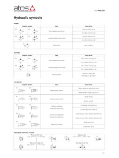
5 For connection to the AC voltage mains, a DC voltage solenoid must be used, which is controlled via a rectifier (see table page 2). A mating connector with integrated rectifier can be used (separate order, see page 13).2) Mating connectors, separate order, see page 13. K4*TAPTAP61574113251711"a"4/14 Bosch Rexroth AG RE 22049 , section, symbols: 2/2 and 3/2 directional seat valveGeneralThe directional valve type is a direct operated direc - tional seat valve with solenoid actuation. It controls start, stop and direction of the flow and basically comprises a housing (1), solenoid (2), valve seats (7) and (11) and closing element (4).The manual override (6) allows for the operation of the valve without solenoid principle (3/2 directional seat valve)The initial position of the valve (normally open UK or nor-mally closed CK ) is determined by the arrangement of the spring (5).
6 The chamber (3) behind the closing element (4) is connected to port P and sealed against port T. Thus, the valve is pressure-compensated in relation to the actuating forces ( solenoid and spring).Due to the special closing element (4), ports P, A, and T can be loaded with the maximum operating pressure (350 bar) and the flow can be directed into both directions (see symbols)!In the initial position, the closing element (4) is pressed onto the seat (11) by the spring (5), in operated position onto the seat (7) by the solenoid (2). The flow is the 2/2 directional seat valve, the tank port is blocked directional seat valve3/2 directional seat valve PK APaabb UK APTaabb NK APaabb CK APTaabbType M-3 SED 6 CK1X/350CG24N9K4 Type M-3 SED 6 UK1X/350CG24N9K4 TBPA810974511162"b"ATBPTPA57411129108 Hydraulics Bosch Rexroth AGRE 22049 , section, symbols, schematic illustration: 4/2 directional seat valveWith a sandwich plate, the Plus-1 plate under the 3/2 direc - tional seat valve, the function of a 4/2 directional seat valve is of the Plus-1 plate Initial position: The main valve is not operated .
7 The spring (5) holds the closing element (4) on the seat (11). Port P is blocked and A connected to T. One pilot line is connected from A to the large area of the pilot spool (8), which is thus unloaded to the tank. The pressure applied via P now pushes the ball (9) onto the seat (10). Thus, P is connected to B, and A to T. Transition position: When the main valve is operated , the closing element (4) is shifted against the spring (5) and pressed onto the seat (7). During this, port T is closed, P, A, and B are briefly con-nected to each other. Spool position: P is connected to A. Because the pump pressure acts via A on the large area of the pilot spool (8), the ball (9) is pressed onto the seat (12).
8 Thus, B is connected to T, and P to A. The ball (9) in the Plus-1 plate has a positive spool overlap .Attention! To prevent pressure intensification in conjunction with single-rod cylinders, the annulus area of the cylinder must be connected to use of the Plus-1 plate and the seat arrangement offer the following options:Symbol D :abABPTabSymbol Y :abABPTabType M-4 SED 6 Y1X/350CG24N9K4 Plus-1 plate3/2 direction-al seat valveSchematic illustration: Initial position6/14 Bosch Rexroth AG RE 22049 data (For applications outside these parameters, please consult us!)1) Suitable for NBR and FKM seals2) Only suitable for FKM seals3) The cleanliness classes specified for the components must be adhered to in hydraulic systems.
9 Effective filtration prevents malfunction and at the same time increases the service life of the components. For selecting the filters, see data sheets RE 50070, RE 50076, RE 50081, RE 50086, RE 50087 and RE ) Special voltages upon request5) Due to the temperatures occurring at the surfaces of the solenoid coils, the standards ISO 13732-1 and EN 982 need to be adhered to!When establishing the electrical connection, the protec-tive earth conductor (PE ) has to be connected 2/2 directional seat valvekg [lbs] [ ] 3/2 directional seat valvekg [lbs] [ ] 4/2 directional seat valvekg [lbs] [ ]Installation positionAnyAmbient temperature range C [ F] 30 to +50 [ 22 to +122] (NBR seals) 20 to +50 [ 4 to +122] (FKM seals)hydraulicMaximum operating pressurebar [psi]See performance limit page 8 Maximum flowl/min [gpm]25 [ ]Hydraulic fluidMineral oil (HL, HLP) according to DIN 51524 1); fast biodegradable hydraulic fluids according to VDMA 24568 (see also RE 90221); HETG (rape seed oil) 1); HEPG (polyglycols) 2); HEES (synthetic esters) 2).
10 Other hydraulic fluids upon requestHydraulic fluid temperature range C [ F] 30 to +80 [ 22 to +176] (NBR seals) 20 to +80 [ 4 to +176] (FKM seals)Viscosity rangemm2/s [SUS] to 500 [35 to 2320]Maximum permitted degree of contamination of the hy-draulic fluid - cleanliness class according to ISO 4406 (c)Class 20/18/15 3)electricalType of voltageDirect voltageAlternate voltageAvailable voltages 4)V12, 24, 42, 96, 110, 205, 220 Only possible via rectifier (see page 13)Voltage tolerance (nominal voltage)% 10 Power consumptionW30 Duty cycle%100 Switching time ac-cording to ISO 6403 ONms40 to 70 OFFms10 to 20 (without rectifier)30 to 45 (with rectifier)Maximum switching frequency Operating pressure 350 bar1/h15000 Operating pressure > 350 bar1/h3600 Type of protection according to DIN EN 60529IP 65 with mating connector mounted and lockedMaximum surface temperature of the spool 5)