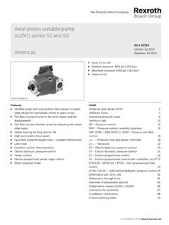
Transcription of Pressure reducing valve, Replaces: 02.03 direct operated
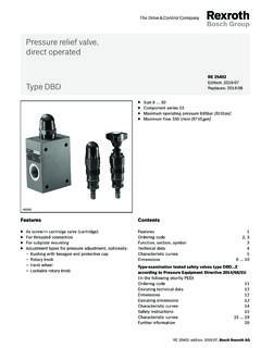
1 1/8 Information on available spare parts: reducing valve, direct operatedType ZDRRE 26570 : of contentsFeatures Sandwich plate valve Porting pattern according to DIN 24340 form A Porting pattern according to ISO 4401-03-02-0-05 (with locating hole) 4 Pressure ratings 4 adjustment types: Rotary knob Bushing with hexagon and protective cap Lockable rotary knob with scale Rotary knob with scale Pressure reduction in channel A, B or channel P Check valve, optional (only version "A")Contents PageFeatures 1 Ordering code 2 Symbols 2 Function, section 3 Technical data 4 Characteristic curves 5 Unit dimensions 6, 7H7750 Size 6 Component series 4 XMaximum operating Pressure 210 barMaximum flow 50 l/minInhaltTable of contents 1 Features 1 Ordering code 2 Symbols ( = component side, = plate side) 2 Function, section 3 Technical data (For applications outside these parameters, please consult us!)
2 4 Characteristic curves (measured with HLP46, oil = 40 5 C) 5 Unit dimensions: Version "B" and "P" (dimensions in mm) 6 Unit dimensions: Version "A" (dimensions in mm) 7 Notes 82/8 Bosch Rexroth AG HydraulicsZDR 6 RE 26570 codeSandwich plate Pressure reducing valveSize 6 = 6 direct operatedPressure reduction in channel A = APressure reduction in channel B = B Pressure reduction in channel P = PAdjustment typeRotary knob = 1 Bushing with hexagon and protective cap = 2 Lockable rotary knob with scale = 3 1)Rotary knob with scale = 7 Component series 40 to 49 = 4X (40 to 49: unchanged installation and connection dimensions)Further details in the plain textNo code = Without locating hole/60 2) = With locating hole/62 = With locating hole and locating pin ISO 8752-3x8-StSeal materialNo code = NBR seals V = FKM seals(other seals upon request) Attention!
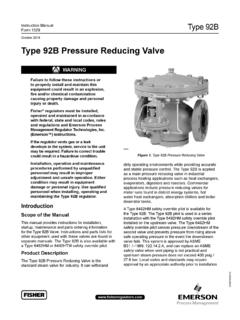
3 Observe compatibility of seals with hydraulic fluid used!No code = With check valve (only with version "A") M = Without check valveY = Pilot oil supply internal, pilot oil return external25 = Secondary Pressure up to 25 bar 75 = Secondary Pressure up to 75 bar 150 = Secondary Pressure up to 150 bar 210 = Secondary Pressure up to 210 barZDR6D4XY*1) H key with material no. R900008158 is included in the ) Locating pin ISO 8752-3x8-St, Material no. R900005694 (separate order)Standard types and standard units are contained in the EPS (standard price list).Symbols ( = component side, = plate side)Type ZDR 6 ZDR 6 ZDR 6 ZDR 6 (Y)43769512812 BPAT(Y)Hydraulics Bosch Rexroth AGRE 26570 ZDR 63/8 Function, sectionThe valve type ZDR is a direct operated Pressure reducing valve in sandwich plate design with Pressure limitation of the secondary circuit.
4 It is used to reduce the system Pressure . The Pressure reducing valve basically comprises of a hous-ing (1), a control spool (2), a compression spring (3), adjust-ment type (4) and an optional check secondary Pressure is set via the adjustment type (4).Version "A"In the initial position the valve is open. Hydraulic fluid can flow from channel A to channel A without limitation. Via the pi-lot line (5), the Pressure in channel A is simultaneously ap-plied to the spool face vis- -vis the compression spring (3). If the Pressure in channel A rises above the value set at the compression spring (3), the control spool (2) moves against the compression spring (3) into the control position and there-by holds the set Pressure in channel A constant.
5 control signal and pilot oil are provided internally, via the con-trol line (5), from channel A .If the Pressure in channel A continues to increase due to external forces at the actuator, the control spool (2) moves further against the compression spring (3).Thus, channel A is, via control edge (9) at the control spool (2) and housing (1) connected with the tank. Hydrau-lic fluid continues to flow to the tank until the Pressure no lon-ger increases. The leakage oil drain from the spring chamber (7) is always realized externally, via bore (6) and channel T (Y).A Pressure gauge connection (8) allows for the control of the secondary Pressure at the version "A", a check valve can be used for free flow back from channel A to A.
6 Versions "P" and "B"With version "P", the Pressure is reduced in channel P . control signal and pilot oil are provided internally, from chan-nel P .With version "B", the Pressure is reduced in channel P , the pilot oil is, however, taken from channel B. Attention!If the directional valve is in spool position P to A, the Pressure in channel B must not exceed the set secondary Pressure . Otherwise, the Pressure in channel A will be reduced. = component side = plate sideType ZDR 6 DA1-4X/. Bosch Rexroth AG HydraulicsZDR 6 RE 26570 data (For applications outside these parameters, please consult us!)generalWeightkgApprox. positionAnyAmbient temperature range C 30 to +80 (NBR seals) 20 to +80 (FKM seals)hydraulicMaximum operating Pressure Inputbar315 Maximum secondary Pressure Outputbar25; 75; 150; 210 Maximum backpressure Port T(Y)bar160 Maximum flowl/min50 Hydraulic fluidSee table belowHydraulic fluid temperature range C 30 to +80 (NBR seals) 20 to +80 (FKM seals)Viscosity rangemm2/s10 to 800 Maximum permitted degree of contamination of the hydraulic fluid - cleanliness class according to ISO 4406 (c)Class 20/18/15 1)1) The cleanliness classes specified for the components must be adhered to in hydraulic systems.
7 Effective filtration pre-vents faults and at the same time increases the service life of the components. For the selection of the filters see fluidClassificationSuitable sealing materialsStandardsMineral oils and related hydrocarbonsHL, HLP, HLPDNBR, FKMDIN 51524 Environmentally compatible Insoluble in waterHETGNBR, FKMISO 15380 HEESFKM Soluble in waterHEPGFKMISO 15380 Flame-resistant Water-freeHFDU, HFDRFKMISO 12922 Water-containingHFC (Fuchs Hydrotherm 46M, Petrofer Ultra Safe 620)NBRISO 12922 Important information on hydraulic fluids! For more information and data on the use of other hydrau-lic fluids refer to data sheet 90220 or contact us!
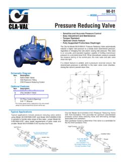
8 There may be limitations regarding the technical valve data (temperature, Pressure range, service life, mainte-nance intervals, etc.)! Flame-resistant water-containing: Maximum operating Pressure 210 bar Maximum hydraulic fluid temperature 60 C Expected service life as compared to HLP hydraulic oil 30 % to 100 %500301010305005010015020025025751502100 0102030405010203012001020304050102030655 0030101030500501001502002502575150210001 02030405010203034 Hydraulics Bosch Rexroth AGRE 26570 ZDR 65/8 Characteristic curves (measured with HLP46, oil = 40 5 C)Flow in l/min Flow in l/min Flow in l/min Flow in l/min Flow in l/min Secondary Pressure in bar Minimum Pressure differential in bar Pressure differential in bar Secondary Pressure in bar Minimum Pressure differential in bar Pressure rating in bar Pressure rating in bar Version "A"pA-qV characteristic curves pmin-qV characteristic curves p-qV characteristic curvesVersion "B" and "P"pA-qV characteristic curves pmin-qV characteristic curvesThe characteristic curves apply to the Pressure at the valve output pT = 0 bar across the entire flow to A 2A to T(Y) (3rd way)3P to P 4P to T(Y) (3rd way)5A to A.
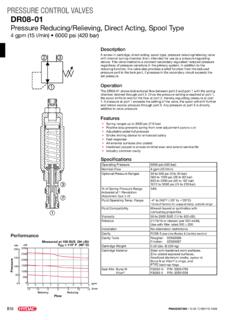
9 Flow only via check valve6A to A ; flow via check valve and completely opened control cross-sectionA to T(Y)A to A P to T(Y)P to P Note!The curve development is maintained according to the Pressure rating if the Pressure is set 11189404019202332091824394 x 5,445 ABPT(Y)4 x 12,2; 1,412,56541110179832; 33523,5F1F2F3F4G84,571220,01/100 Rzmax 46/8 Bosch Rexroth AG HydraulicsZDR 6 RE 26570 dimensions: Version "B" and "P" (dimensions in mm) Component side porting pattern according to DIN 24340 form A (without locating hole), or ISO 4401-03-02-0-05 (with locating hole 3 x 5 mm deep) Plate side porting pattern according to DIN 24340 form A (without locating hole), or ISO 4401-03-02-0-05 (with locating hole for locating pin ISO 8752-3x8-St.)
10 Version "/60")1 Name plate2 Adjustment type "1"3 Adjustment type "2"4 Adjustment type "3"5 Adjustment type "7"6 Space required to remove the key7 Valve mounting bores8 Lock nut SW249 Hexagon SW1010 Identical seal rings for ports A, B, P, T(Y)11 Pressure gauge connection G1/4; 12 deep; internal hexagon SW6 Required surface quality of the valve mounting faceValve mounting screws (separate order)4 hexagon socket head cap screws ISO 4762 - M5 - Note!Length and tightening torque of the valve mounting screws must be calculated according to the components mounted un-der and over the sandwich plate 1118940401920233209182412,56541110179832 ; 335394 x 5,445 ABPT(Y)4 x 12,2.