Transcription of 4/2- and 4/3-way proportional
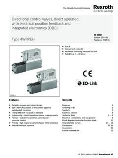
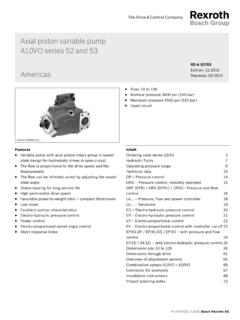
1 1/16 For information regarding the available spare parts and 4/3-way proportional directional valves, direct operated, without electrical position feedback, without/with integrated electronics (OBE)Types 4 WRA and 4 WRAEN ominal sizes 6 and 10 Component series 2 XMaximum operating pressure 315 barMaximum flow: 42 l/min (NS6) 75 l/min (NS10)RE 29055 Replaces: 4 WRA 10 ..-2 with plug-in connectors and associated control electronics (separate order)Type 4 WRAE 6 ..-2X/G24K31/.Vwith integrated electronics (OBE)H5964H4678 Overview of contentsContents PageFeatures 1 Ordering details 2 Symbols 3 Function, section 4 Technical data 5, 6 Control electronics 6 Electrical connections, plug-in connectors 7 Integrated electronics (OBE) for type 4 WRAE 8 Characteristic curves dimensions 12.
2 15 Features Direct operated proportional directional valve without electrical position feedback and integrated electronics (OBE) for type 4 WRAE Control the direction and magnitude of a flow Actuation by means of proportional solenoids with central thread and removable coil For subplate mounting: Connection position to ISO 4401 Subplates to catalogue sheets RE 45052 (NS6) or RE 45054 (NS10) separate order, see page 12 to 15 Spring centred control spool Control electronics 4 WRAE: - integrated electronics (OBE) with voltage input or current input (A1 resp. F1) 4 WRA: - digital or analogue amplifier in Eurocard format (separate order) - analogue module amplifier 2/16 Bosch Rexroth AG Hydraulics4 WRA; 4 WRAE RE 29055 detailsWithout integratedelectronics (OBE) = No codeWith integratedelectronics (OBE) = E Nominal size 6 = 6 Nominal size 10 = 10 Spool symbolsPTa0bABa0 ABPT= E E1 = W W1 = EA= WAWith spool symbols E1 and W1 :P A: qV max B T: qV/2P B: qV/2 A T: qV maxNote:With spools W and WA, in the neutral position, there is a connection from A to T and B to T with approx.
3 3 % of the relevant nominal cross-section. Further details in clear textSeal materialV = FKM seals, suitable for mineral oil (HL, HLP) to DIN 51524 Electronic interfaces A1 or F1 for 4 WRAEA1 = Command value input 10 VF1 = Command value input 4 to 20 mANo code = For 4 WRAE lectrical connectionsfor 4 WRA:K4 2) = Without plug-in connector, with component plug to DIN EN 175301-803plug-in connector separate order,see page 7 for 4 WRAE:K31 2) = Without plug-in connector, with component plug to DIN EN 175201-804plug-in connector separate order,see page 7 Special protectionNo code = Without special protectionJ 1) = Sea water resistant (only for NS6)For details regarding the sea water resistant versions see RE 29055-MG24 = Supply voltage 24 VDC2X = Component series 20 to 29(20 to 29: unchanged installation and connection dimensions)Nominal flow at a valve pressure differential p = 10 barNS607 = 7 l/min15 = 15 l/min30 = 26 l/minNS1030 = 30 l/min60 = 60 l/min4 WRA2X G24V*1) Other types of electrical protection on request2) Only for NS6: for version "J" = sea water resistant only state "K31"!
4 ABPTa0abABPTa0abABPTa0babABPTa0babHydrau lics Bosch Rexroth AGRE 29055 4 WRA; 4 WRAE3/16 SymbolsWithout integrated electronicsType ; integrated electronics (OBE)Type ; (P) a b a b Bosch Rexroth AG Hydraulics4 WRA; 4 WRAE RE 29055 , sectionThe 4/2- and 4/3-way proportioanl directional valves are designed as direct operated components for subplate mounting. They are actuated by means of proportional solenoids with central thread and removable coil. The solenoids are controlled either by external control electronics (type 4 WRA) or by integrated control electronics (type 4 WRAE).Design:The valves basically consist of: Housing (1) with mounting surface Control spool (2) with compression springs (3 and 4) Solenoids (5 and 6) with central thread Optional integrated electronics (7)Valve with 2 spool positions:(Type )In principle, the function of this valve version corresponds to that of the valve with 3 spool positions.
5 However, the valves with 2 spool positions are only fitted with solenoid "a". In-stead of the the 2nd proportional solenoid a plug ( ) is fitted for NS 6 or for NS 10 a cover ( ).Function: With the solenoids (5 and 6) de-energised, the control spool (2) is held in the central position by compression springs (3 and 4) Direct actuation of the control spool (2) by energising a proportional energinsaion of solenoid "b" (6) The control spool (2) is moved to the left in proportion to the electrical input signal connection from P to A and B to T via orifice-like cross- sections with progressive flow characterisics De-energisation of the solenoid (6) The control spool (2) is returned to the central position by compression spring (3) Type 4 WRA 4 WRAE Note for type 4 WRA :Draining of the tank line is to be avoided.
6 With the appropriate installation conditions, a back pressure valve is to be installed (back pressure approx. 2 bar). Hydraulics Bosch Rexroth AGRE 29055 4 WRA; 4 WRAE5/16 Technical data (for applications outside these parameters, please consult us!)GeneralNominal sizeNS610 Installationoptional, preferably horizontalStorage temperature range C 20 to +80 Ambient4 WRA C 20 to +70temperature range4 WRAE C 20 to + (measured with HLP46, oil = 40 C 5 C)Max. operating pressurePorts A, B, Pbar315 Port Tbar210 Nominal flow qV nom at p = 10 barl/min7, 15, 2630, 60 Max. permissible flowl/min42 (80)1)75 (140)1)Pressure fluidmineral oil (HL, HLP) to DIN 51524 other pressure fluids on request!Pressure fluid temperature range C 20 to +80 (preferably +40 to +50)Viscosity rangemm2/s20 to 380 (preferably 30 to 46)Max.
7 Permissible degree of pressure fluid contaminationcleanlisness class to ISO 4406 (c)class 20/18/15 2)Hysteresis% 5 Reversal error% 1 Response sensitivity% ) Max. permissible flow with a dual flow path 2) The cleanliness class stated for the components must be adhered too in hydraulic systems. Effective filtration prevents faults from occurring and at the same time increases the component service the selection of filters see catalogue sheets RE 50070, RE 50076, RE 50081, RE 50086 and RE Bosch Rexroth AG Hydraulics4 WRA; 4 WRAE RE 29055 data (for applications outside these parameters, please consult us!)ElecticalNominal sizeNS610 Voltage typeDCCommand value signal Voltage input A1 V 10with type WRAEC urrent input F1 mA4 to 20 Max.
8 Current per coilCold value at 20 C 2resistanceMax. warm value 3 Duty%100 Max. coil temperature 1) C150 Electrical connections 4 WRAwith component plug to DIN EN 175301-803 or ISO 4400see page 7plug-in connector to DIN EN 175301-803 or ISO 4400 2)4 WRAE with component plug to DIN EN 175201-804plug-in connector DIN EN 175201-804 2)Valve protection to EN 60529IP65 with mounted and fixed plug-in connectorControl electronicsFor 4 WRAD igital amplifier in Eurocard format 2)VT-VSPD-1-2X ( to RE 30523 - middle of 2006)Analogue amplifier in Eurocard format 2)VT-VSPA2-1-2X/.. to RE 30110 Analogue module amplifier 2)VT-MSPA2-1-1X to RE 30228 For 4 WRAE integrated into the valves, see page 8 Analogue command value moduleVT- SWMA-1-1X/.
9 To RE 29902 Analogue command value moduleVT-SWMKA-1-1X/.. to RE 29903 Digital command value cardVT-HACD-1-1X/.. to RE 30143 Analogue command value cardVT-SWKA-1-1X/.. to RE 30255 Supply voltageNominal voltageVDC244 WRAE, 4 WRA 3)Lower limiting valueV21 / 22 (4 WRA); 19 (4 WRAE)Upper limiting valueV35 Amplifier impulse currentA31) Due to the occurring surface temperature of the solenoid coils, the European Standards DIN EN 563 and DIN EN 982 must be taken into account!2) Separate order3) With Bosch Rexroth AG control electronics Note: For details regarding the environmental simulation test covering EMC (electro- magnetic compatibility), climate and mechanical loading see RE 29055-U (declaration regarding environmental compatibility).
10 PE12PE12PE12PE1227,518431034,25,511210A2 50 VGDM1 Fixing screws M3 Tightening torque MA = NmAFEDCB 6, 2791 13,585 Hydraulics Bosch Rexroth AGRE 29055 4 WRA; 4 WRAE7/16 Electrical connection, plug-in connectorsFor type WRA(without integrated electronics not for version "J" = sea water resistant)Plug-in connector CECC 75 301-803-A002FA-H3D08-G to DIN EN 175301-803 or ISO 4400 Solenoid a, colour greySeparate order: Material No. R901017010 Solenoid b, colour blackSeparate order: Material No. R901017011 For type WRAE(with integrated electronics (OBE) and for version "J" = sea water resistant)For pin allocation, see block circuit diagram on page 8 Plug-in connector to DIN EN 175201-804 Separate order: Material No. R900021267 (plastic version)To amplifierTo amplifierPlug-in connector to DIN EN 175201-804 Separate order: Material No.