Transcription of 2.9.31. PARTICLE SIZE ANALYSIS BY LASER LIGHT …
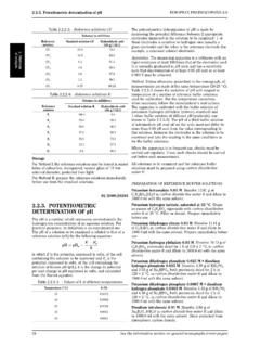
1 EUROPEAN PHARMACOPOEIA PARTICLE size ANALYSIS by LASER LIGHT diffraction the cumulative amount dissolved at each time point divided This chapter provides guidance for the measurement of size by the surface area exposed. Linear regression is then distributions of particles in different dispersed systems, for performed on the normalised experimental data relevant example, powders, sprays, aerosols, suspensions, emulsions, to an appropriate time interval preceding the possible and gas bubbles in liquids, through ANALYSIS of their angular disintegration of the compact.
2 The intrinsic dissolution rate LIGHT -scattering patterns. It does not address specific of the substance tested, expressed in milligrams per minute requirements of PARTICLE size measurement of specific per square centimetre, is determined from the slope of the products. regression line. The result for intrinsic dissolution rate must be accompanied by a statement of the precise conditions of PRINCIPLE. compact preparation and test method (dissolution medium, volume of medium used, stirring rate, temperature etc.). A representative sample, dispersed at an adequate concentration in a suitable liquid or gas, is passed through NOTE : when necessary and justified, an apparatus with a a beam of monochromatic LIGHT , usually a LASER .
3 The LIGHT different configuration may be used, such as a die holder that scattered by the particles at various angles is measured by a holds the compact in a fixed vertical position, with agitation multi-element detector. Numerical values representing the provided by a paddle positioned at a defined distance from scattering pattern are then recorded for subsequent ANALYSIS . the surface of the compact. These scattering pattern values are then transformed, using an appropriate optical model and mathematical procedure, to 01/2008:20931.
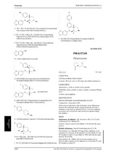
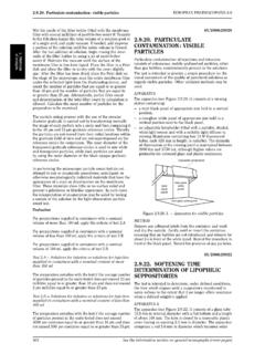
4 Yield the proportion of total volume to a discrete number of size classes, forming a volumetric PARTICLE -size distribution. PARTICLE SIZE ANALYSIS . BY LASER LIGHT DIFFRACTION APPARATUS. The method is based on the ISO standards 13320-1(1999) An example of a set-up of a LASER LIGHT diffraction instrument and 9276-1(1998). is given in Figure Other equipment may be used. INTRODUCTION The instrument comprises a LASER LIGHT source, beam processing optics, a sample measurement region (or cell), a The LASER LIGHT diffraction technique used for the Fourier lens, and a multi-element detector for measuring the determination of PARTICLE -size distribution is based on the scattered LIGHT pattern.
5 A data system is also required for ANALYSIS of the diffraction pattern produced when particles deconvolution of the scattering data into a volumetric size are exposed to a beam of monochromatic LIGHT . Historically, distribution and associated data ANALYSIS and reporting. the early LASER diffraction instruments only used scattering at small angles. However, the technique has since been The particles can enter the LASER beam in 2 positions. In broadened to include LASER LIGHT scattering in a wider angular the conventional case the particles enter the parallel beam range and application of the Mie theory, in addition to the before the collecting lens and within its working distance.
6 In Fraunhofer approximation and anomalous diffraction. so-called reversed Fourier optics the particles enter behind The technique cannot distinguish between scattering the collecting lens and thus, in a converging beam. The by single particles and scattering by clusters of primary advantage of the conventional set-up is that a reasonable particles, by agglomerates or aggregates. As most path length for the sample is allowed within the working particulate samples contain agglomerates or aggregates and distance of the lens. The second set-up allows only small path as the focus of interest is generally on the size distribution lengths but enables measurement of scattered LIGHT at larger of primary particles, the clusters are usually dispersed into angles, which is useful when submicron particles are present.
7 Primary particles before measurement. The interaction of the incident LIGHT beam and the ensemble For non-spherical particles, an equivalent sphere-size of dispersed particles results in a scattering pattern with distribution is obtained because the technique assumes different LIGHT intensities at various angles. The total angular spherical particles in its optical model. The resulting intensity distribution, consisting of both direct and scattered PARTICLE -size distribution may differ from those obtained LIGHT , is then focused onto a multi-element detector by a lens by methods based on other physical principles ( or a series of lenses.)
8 These lenses create a scattering pattern sedimentation, sieving). that, within limits, does not depend on the location of the 1. Obscuration detector 5. Scattered LIGHT not collected by lens (4) 9. Working distance of lens (4). 2. Scattered beam 6. PARTICLE ensemble 10. Multi-element detector 3. Direct beam 7. LIGHT source LASER 11. Focal distance of lens (4). 4. Fourier lens 8. Beam processing unit Figure - Example of a set-up of a LASER LIGHT diffraction instrument General Notices (1) apply to all monographs and other texts 311.
9 PARTICLE size ANALYSIS by LASER LIGHT diffraction EUROPEAN PHARMACOPOEIA particles in the LIGHT beam. Hence, the continuous angular Optimisation of the liquid dispersion. Liquids, surfactants, intensity distribution is converted into a discrete spatial and dispersing aids used to disperse powders must : intensity distribution on a set of detector elements. be transparent at the LASER wavelength and practically free It is assumed that the measured scattering pattern of the from air bubbles or particles ;. PARTICLE ensemble is identical to the sum of the patterns from have a refractive index that differs from that of the test all individual single scattering particles presented in random material.
10 Relative positions. Note that only a limited angular range be non-solvent of the test material (pure liquid or of scattered LIGHT is collected by the lens(es) and, therefore, pre-filtered, saturated solution) ;. by the detector. not alter the size of the test materials ( by solubility, DEVELOPMENT OF THE METHOD solubility enhancement, or recrystallisation effects) ;. Traditionally, the measurement of PARTICLE size using LASER favour easy formation and stability of the dispersion ;. diffraction has been limited to particles in the range of be compatible with the materials used in the instrument approximately m to 3 mm.