Transcription of 21 COMPOSITE BEAMS – I - steel-insdag.org
1 COMPOSITE BEAMS - I COMPOSITE BEAMS I 21 INTRODUCTION In conventional COMPOSITE construction, concrete slabs rest over steel BEAMS and are supported by them. Under load these two components act independently and a relative slip occurs at the interface if there is no connection between them. With the help of a deliberate and appropriate connection provided between the beam and the concrete slab, the slip between them can be eliminated.
2 In this case the steel beam and the slab act as a COMPOSITE beam and their action is similar to that of a monolithic Tee beam. Though steel and concrete are the most commonly used materials for COMPOSITE BEAMS , other materials such as pre-stressed concrete and timber can also be used. Concrete is stronger in compression than in tension, and steel is susceptible to buckling in compression. By the COMPOSITE action between the two, we can utilise their respective advantages to the fullest extent. Generally in steel -concrete COMPOSITE BEAMS , steel BEAMS are integrally connected to prefabricated or cast in situ reinforced concrete slabs.
3 There are many advantages associated with steel concrete COMPOSITE construction. Some of these are listed below: The most effective utilisation of steel and concrete is achieved. Keeping the span and loading unaltered; a more economical steel section (in terms of depth and weight) is adequate in COMPOSITE construction compared with conventional non- COMPOSITE construction. As the depth of beam reduces, the construction depth reduces, resulting in enhanced headroom. Because of its larger stiffness, COMPOSITE BEAMS have less deflection than steel BEAMS . COMPOSITE construction provides efficient arrangement to cover large column free space.
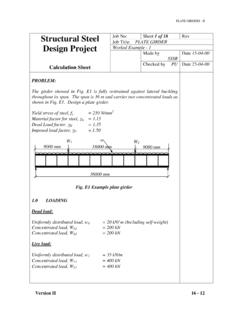
4 COMPOSITE construction is amenable to fast-track construction because of using rolled steel and pre-fabricated components, rather than cast-in-situ concrete. Encased steel beam sections have improved fire resistance and corrosion. ELASTIC BEHAVIOUR OF COMPOSITE BEAMS The behaviour of COMPOSITE BEAMS under transverse loading is best illustrated by using two identical BEAMS , each having a cross section of b h and spanning a distance of , one placed at the top of the other. The BEAMS support a uniformly distributed load of w/unit length as shown in Fig 1.
5 For theoretical explanation, two extreme cases of no interaction and 100% (full) interaction are analysed below: Copyright reserved Version II 21-1 COMPOSITE BEAMS - I Fig. 1. Effect of shear connection on bending and shear stresses No Interaction Case It is first assumed that there is no shear connection between the BEAMS , so that they are just seated on one another but act independently. The moment of inertia (I) of each beam is given by bh3/12.
6 The load carried by each beam is w/2 per unit length, with mid span moment of w 2/16 and vertical compressive stress of w/2b at the interface. From elementary beam theory, the maximum bending stress in each beam is given by, )1(8322maxbhwIMyf == where, M is the maximum bending moment and ymax is the distance to the extreme fibre equal to h/2. The maximum shear stress (qmax) that occurs at the neutral axis of each member near support is given by bhwbhwq831423max == (2) Version II 21-2 COMPOSITE BEAMS - I and the maximum deflection is given by )3(645384)2/( The bending moment in each beam at a distance x from mid span is, 5344 EbhwEIw = x = =M)4(16/)
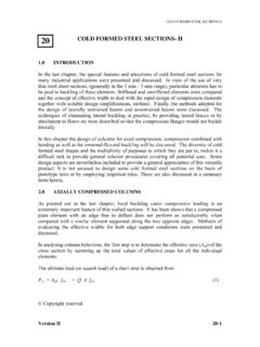
7 4(22xwSo, the tensile strain at the bottom fibre of the upper beam and the compression stress at the top fibre of the lower beam is, )5(8)4(3222maxEbhxwEIMyx == /2 - /2 Fig. 2. Typical Deflections, slip strain and slip. Version II 21-3 COMPOSITE BEAMS - I Hence the top fibre of the bottom beam undergoes slip relative to the bottom fibre of the top beam. The slip strain the relative displacement between adjacent fibres is therefore 2x.)
8 Denoting slip by S, we get, )6(4)4(32222 EbhxwdxdSx == Integrating and applying the symmetry boundary condition S = 0 at x = 0 we get the equation )7(4)43(232 EbhxxwS = The Eqn. (6) and Eqn. (7) show that at x = 0, slip strain is maximum whereas the slip is zero, and at x= /2, slip is maximum whereas slip strain is zero. This is illustrated in Fig 2. The maximum slip ( Smax = w 3/4 Ebh2) works out to be times the maximum deflection of each beam derived earlier. If /(2h) of BEAMS is 20, the slip value obtained is times the maximum deflection. This shows that slip is a very small in comparison to deflection of beam.
9 In order to prevent slip between the two BEAMS at the interface and ensure bending strain compatibility shear connectors are frequently used. Since the slip at the interface is small these shear connections, for full COMPOSITE action, have to be very stiff. Full (100%) interaction case Let us now assume that the BEAMS are joined together by infinitely stiff shear connection along the face AB in Fig. 1. As slip and slip strain are now zero everywhere, this case is called full interaction . In this case the depth of the COMPOSITE beam is 2h with a breadth b, so that I = 2bh3/3. The mid-span moment is w 2/8.
10 The maximum bending stress is given by )8(1632382232maxmaxbhwhbhwIMyf === This value is half of the bending stress given by Eqn. (1) for no interaction case . The maximum shear stress qmax remains unaltered but occurs at mid depth. The mid span deflection is )9(256534 Ebhw = This value of deflection is one fourth of that of the value obtained from Eqn. (3). Thus by providing full shear connection between slab and beam, the strength and stiffness of the system can be significantly increased, even though the material consumption is essentially the same.