Transcription of 22 COMPOSITE BEAMS – II
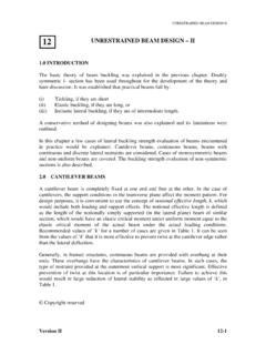
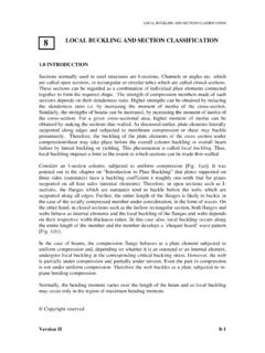
1 DESIGN OF COMPOSITE BEAMS -II. COMPOSITE BEAMS II. 22. INTRODUCTION. A steel concrete COMPOSITE beam consists of a steel beam, over which a reinforced concrete slab is cast with shear connectors, as explained in the previous chapter. Since COMPOSITE action reduces the beam depth, rolled steel sections themselves are found adequate frequently (for buildings) and built-up girders are generally unnecessary. The COMPOSITE beam can also be constructed with profiled sheeting with concrete topping, instead of cast-in place or precast reinforced concrete slab. The profiled sheets are of two types Trapezoidal profile Re-entrant profile (a) Trapezoidal profile (b) Re-entrant profile Fig. 1 Types of profile deck These two types are shown in Fig 1. The profiled steel sheets are provided with indentations or embossments to prevent slip at the interface.
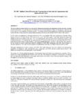
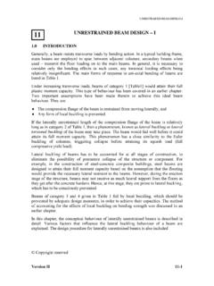
2 The shape of the re-entrant form, itself enhances interlock between concrete and the steel sheet. The main advantage of using profiled deck slab is that, it acts as a platform and centering at construction stage and also serves the purpose of bottom reinforcement for the slab. (a) Ribs parallel to the beam (b) Ribs perpendicular to the beam Fig. 2. Orientation of Profiled deck slab in a COMPOSITE beam Copyright reserved Version II 22 - 1. DESIGN OF COMPOSITE BEAMS -II. The deck slab with profiled sheeting is of two types (see Fig 2). The ribs of profiled decks running parallel to the beam The ribs of profiled decks running perpendicular to the beam. PROVISION FOR SERVICE OPENING IN COMPOSITE BEAMS . There is now a growing demand for longer spans, either for open plan offices, or to permit greater flexibility of office layout, or for open exhibition and trading floors.
3 For these longer spans, the choice of structural form is less clear cut largely on account of the need for providing for services satisfactorily. Service openings can be easily designed in conventional rolled steel BEAMS . Conventional construction may still be appropriate, but other, more novel, structural forms may offer economy or other overriding advantages, besides easy accommodation of services. Open web joist floor system may be one such solution for longer span (see the chapter on trusses). In fact, many of these were developed in Great Britain and a number of Design Guides have been produced by the Steel Construction Institute. Simple Construction with Rolled Sections(1). For spans in the range of 6 to 10 m, perhaps the most appropriate form of construction is rolled sections and simple, shear only connections. Secondary BEAMS at m or m centres support lightweight COMPOSITE floor slabs and span onto primary BEAMS , which in turn frame directly into the columns.
4 The same form of construction may also be used for longer span floors but beam weights and costs increase to the point where other forms of construction may be more attractive. Of increasing concern to developers is the provision of web openings as these are inflexible and they can create difficulties in meeting the specific needs of tenants or in subsequent reservicing during the life of the structure. Fabricated Sections(2). The use of fabricated sections for multi-storey buildings has been explored by some This usage became economic with advances in the semi-automatic manufacture of plate girder sections. Different approaches to manufacture have been developed by different fabricators . Significant savings in weight can be achieved due to the freedom, within practical limits, to tailor the section to suit its bending moment and shear force envelopes.
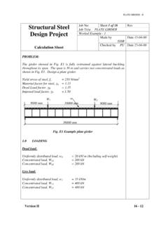
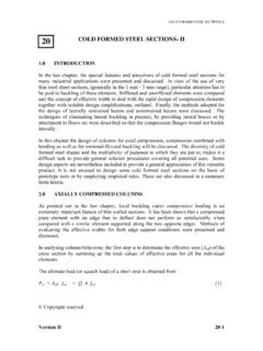
5 Depth, taper and shape flange size and web thickness may all be selected independently by the designer . Fabricated sections are most likely to be economic for spans above 12 m. Above this span length, rolled sections are increasingly heavy and a fine-tuned fabricated section is likely to be able to save on both flange size and web thickness. With some manufacturing processes, asymmetric sections with narrow top flanges can be adopted, achieving further weight savings. Version II 22 - 2. DESIGN OF COMPOSITE BEAMS -II. The freedom to tailor the fabrication to the requirements of the designer allows the depth of the girder to be varied along its length and to allow major services to run underneath the shallower regions. A range of shapes is feasible (see ) of which the semi-tapered beam is the most efficient structurally but can only accommodate relatively small ducts.
6 The straight-tapered BEAMS shown in Fig 3(a) offers significantly more room for ducts, at the expense of some structural efficiency, and has proved to be the most popular shape to date. Cranked taper BEAMS can also be used, providing a rectangular space under the BEAMS at their ends. Fabricated BEAMS are often employed to span the greater distance, and supporting shorter span primary BEAMS of rolled sections. (a) Straight Taper (b) Semi-Taper (c)Cranked Taper (d) Stepped Beam (where automatic welding is not crucial). Fig. 3. Fabricated sections for commercial buildings Haunched BEAMS (3). In traditional multi-storey steel frames, the conventional way to achieve economy is to use simple' design. In a long span structure, there is perhaps twice the length of primary BEAMS compared to the columns and for a low rise building their mass/metre will be comparable.
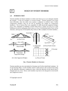
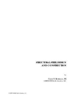
7 In these circumstances the economic balance may shift in favour of sacrificing column economy in order to achieve greater beam efficiency by having moment resisting connections. The benefits of continuity are particularly significant when stiffness rather than the strength governs design, and this is increasingly likely as spans increase. Where fully rigid design is adopted, the beam to column connection is likely to have to develop the hogging bending capacity of the COMPOSITE section. Until our design concepts on COMPOSITE connections are more fully developed, designers have to rely on an all-steel connection and this will usually require substantial stiffening and could prove to be expensive. The most straightforward way to reduce connection costs is to use some form of haunched connection (Fig. 4); they occupy the region below the beam, which is anyway necessary for the main service ducts.
8 (With haunched BEAMS , the basic section is usually Version II 22 - 3. DESIGN OF COMPOSITE BEAMS -II. too shallow for holes to be formed in its web that are sufficiently large to accommodate main air-conditioning ducts). Thus the haunches simplify BEAMS of column connection significantly and improve beam capacity and stiffness without increasing the overall floor depth. (a) sections of different size (b) haunches cut from main beam Fig. 4 Haunched BEAMS : Two types of haunches Parallel Beam Approach(4). In the parallel beam approach, it is the secondary BEAMS that span the greater distance. A. very simple form of construction results as they run over the primary BEAMS and achieve continuity without complex connections (see Fig. 5). Fig. 5. Parallel beam grillage The primary or spine BEAMS also achieve continuity by being used in pairs with one beam passing on either side of the columns.
9 Shear is transferred into the columns by means of brackets. This offset' construction, where members are laid out in the three orthogonal directions deliberately to miss each other enable continuity of the BEAMS to be achieved without the high cost of moment resisting connections; this improves the structural efficiency and (of particular importance for long span construction) stiffness. There is also a considerable saving of both erection time and erection cost. Because continuity is such an integral part of the approach, it is primarily applicable for multi-bay layouts. Version II 22 - 4. DESIGN OF COMPOSITE BEAMS -II. Superficially, the approach appears to lead to deeper construction. However, because of continuity, the primary and secondary BEAMS can both be very shallow for the spans and overall depths are comparable with conventional construction.
10 Most importantly, the separation of the two beam directions into different planes creates an ideal arrangement for the accommodation of services. Castellated Sections (5). Castellated BEAMS are made from Rolled Steel BEAMS by fabricating openings in webs, spaced at regular intervals. Castellated sections have been used for many years (see ). as long span roof BEAMS where their attractive shape is often expressed architecturally. The combination of high bending stiffness and strength per unit weight with relatively low shear capacity is ideal for carrying light loads over long spans. As COMPOSITE floor BEAMS , their usage is limited by shear capacity. These are generally unsuitable for use as primary BEAMS in a grillage, because the associated shears would require either stiffening to or infilling of the end openings, thereby increasing the cost to the point that other types of BEAMS become economical.