Transcription of 24. Force Main Design. - wsscwater.com
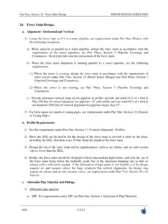
1 Part Two, Section 24. Force main design SEWER design GUIDELINES 2008 24. Force main design . a. Alignment - Horizontal and Vertical 1) Locate the Force main as if it is a water pipeline, see requirements under Part One (Water), with the following exceptions. a) When adjacent or parallel to a water pipeline, design the Force main in accordance with the requirements of the sewer pipelines, see Part Three, Section 3 (Pipeline Crossings and Clearances). Do not provide concrete encasement of the Force main . b) When the Force main alignment is running parallel to a sewer pipeline, see the following requirements: (1) Where the sewer is existing, design the Force main in accordance with the requirements of relief sewers under Part Two, Section 23 (Relief Sewer design ) and Part Three, Section 3 (Pipeline Crossings and Clearances). (2) Where the sewer is not existing, see Part Three, Section 3 (Pipeline Crossings and Clearances).
2 C) Provide minimum vertical slope on the pipeline in profile: provide one tenth ( ) of a foot in fifty (50) feet of vertical alignment for pipelines 12" and smaller and one tenth ( ) of a foot in one hundred (100) feet of vertical alignment for pipelines larger than 12". 2) For Force mains in tunnels or casing pipes, see requirements under Part One, Section 18 (Tunnels or Casing Pipes). b. Profile Requirements. 1) See the requirements under Part One, Section 11 (Vertical Alignment - Profile). 2) Show the HGL on the profile for the design of the Force main or provide a table on the plans, providing the HGL elevation every 50 feet along the length of the Force main . 3) design the top of the Force main and its appurtenances, such as air release, and air and vacuum valves, lower than the HGL. 4) Ideally, the Force main should be designed without intermediate high points, and with the top of the Force main being below the hydraulic grade line at the minimum pumping rate so that air release valves will not be needed.
3 If the elimination of high points is not feasible or if the design requires air and vacuum valves, for long, relatively flat vertical alignments, the design may require air release and air and vacuum valves, see requirements under Part Two, Section 26 (Air Valves). c. Allowable Pipe Material and Fittings. 1) Allowable pipe material. a) DIP. For requirements using DIP, see Part One, Section 4 (Selection of Pipe Material). Part Two, Section 24. Force main design SEWER design GUIDELINES 2008 b) AWWA C900 PVC. May be used for Force mains in diameters 12-inch and smaller as an alternative to DIP if the PVC pipe meets the external load and internal pressure requirements, as stated in this section. (1) Pipe dimension ratio for AWWA C900 PVC. The use of PVC for Force mains is limited by the pipe diameter, operating pressure (including pump cyclic loading), and pipe dimension ratio (DR) as follows: (a) AWWA C900 DR18, total allowable internal pressure, operating plus surge, not to exceed one hundred sixty (160) psi, except as noted in Pumping cyclic loading, in this section.
4 (b) AWWA C900 DR14, total allowable internal pressure, operating plus surge, not to exceed two hundred five (205) psi, except as noted in Pumping cyclic loading, in this section. (c) Pumping cyclic loading. [1] The on/off operation of pumps creates a cyclic loading, which may limit the total allowable pressure in the Force main . Information on cyclic loading is available from the UniBell PVC Pipe Association. [2] Confirm the number of pump "on" and "off's" during the life of the forcemain and submit calculations indicating whether total allowable pressure has to be reduced to account for cyclic loading. For purposes of this design criteria, use the following equations for finding the total allowable internal pressure: DR18 pipe. The maximum total internal pressure = 2768 Where C is the number of pump "on" and "off's during the life of the forcemain. Example: Assuming a pump operates twice per hour (4 "on" and "off's") 24 hours per day, 365 days per year for 75 years.
5 Then C = 4 24 365 75 = 2,628,000. The maximum total internal pressure = 2768 2,628, = 135 psi. DR14 pipe. The maximum total internal pressure = 3618 Where C is the number of pump "on" and "off's" during the life of the forcemain. Example: Assuming a pump operates twice per hour (4 "on" and "off's") 24 hours per day, 365 days per year for 75 years. Then C = 4 24 365 75 = 2,628,000. The maximum total internal pressure = 3618 2,628, = 177 psi. The above equations for the DR14 and DR18 for cyclic loading include a derating factor assuming a wastewater temperature of 80 degrees. (2) Allowable cover for AWWA C900 PVC. (a) AWWA C900 DR18, allowable cover is ten (10) feet. If DR 18 pipe is encased in granular material in accordance with the Specifications for PVC Gravity Sewer Pipe and Standard Detail , maximum allowable cover is twenty two (22) feet. (b) AWWA C900 DR14, allowable cover is twenty five (25) feet.
6 If the DR 14 pipe is encased in granular material in accordance with the Specifications for PVC Gravity Part Two, Section 24. Force main design SEWER design GUIDELINES 2008 Sewer Pipe and Standard Detail , maximum allowable cover is forty (40) feet. (c) The allowable cover with native bedding/backfill is based on a soil modulus of 0, deflection lag factor of , earth load calculated as prism load, and maximum allowable deflection (3) Information required on the Drawings. (a) Indicate the allowable type(s) of pipe; DIP and/or AWWA C900 PVC. (b) If AWWA C900 PVC is allowed, the specifications require DR18 pipe, unless noted otherwise on the drawings. Calculate the maximum operating pressure and surge, and assure that the operating and surge pressure is less than one hundred sixty (160) psi and adjusted for cyclic loading. If greater than one hundred sixty (160) psi, but less than 205 psi and adjusted for cyclic loading, add a note to the drawings requiring DR14.
7 In considering surge, note that the modulus of elasticity of PVC is much less than that for DIP and therefore, for a given change in velocity, the resulting surge is less for PVC than DIP. Consult the Unibell PVC Pipe Handbook for additional information. (c) If granular material bedding is required due to the depth of cover, see "Allowable cover for AWWA C900 PVC" in this section, and include a note to provide bedding for the PVC according to Standard Detail 2) Allowable fittings for AWWA C900 PVC. a) Limit the type of fittings on the Force main to only bends, see allowable fitting requirements under Part One, Section 7 (Allowable Fittings). b) For DIP, see allowable fittings in accordance with Part One, Section 2 (Pipe Materials and Fittings). c) For AWWA C900, the allowable fittings according to the Specifications can be PVC push-on or ductile iron or cast iron in accordance with Part One, Section 2 (Pipe Materials and Fittings).
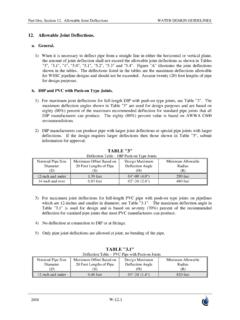
8 Restrained joints require ductile iron mechanical joint fittings. 3) Thrust restraint for AWWA C900 PVC. a) For thrust restraint, concrete thrust blocks are the preferred method of restraint. If blocking is not possible, restrained joints may be used, see "Allowable fittings for AWWA C900 PVC", in this section. b) design the thrust restraint, in accordance with Part Three, Section 27 (Thrust Restraint design for Buried Piping). 4) design criteria for AWWA C900 PVC. a) design the PVC C900 pipeline without curves using fittings only. See Part One, Section 12 (Allowable Joint Deflections) and Part One, Section 14 (Joint Deflections at Fittings). b) Field bending of PVC pipe is not permitted and the manufacturers allowable PVC pipe joint deflection is limited. See Part One, Section 13 (Allowable Joint Deflections). Do not deflect PVC pipe in a restrained joint system. If deflection is required in a restrained joint, use Part Two, Section 24.
9 Force main design SEWER design GUIDELINES 2008 ductile iron pipe. d. Appurtenances and Structures. 1) Air release, and air and vacuum valves, see requirements under Part Two, Section 26 (Air Valves) and Profile Requirements, in this section. 2) Blowoffs. a) Locate blowoffs near the wastewater pumping station. The wastewater pumping station by-pass piping may be used to blowoff the Force main piping, see WSSC design Guidelines for Wastewater Pumping Stations (DG-06). b) Blowoffs along the Force main normally are not required, however, where the Force main contains a long depressed section between two high points or in case the Force main needs a point to drain the system, WSSC may require a blowoff. The design of blowoff piping consists of a valve connection on the Force main and piping to either a gravity sewer manhole or to a manhole so that a pump can be used to drain the Force main to a gravity sewer manhole, tank truck, etc.
10 3) Provide flushing connections on the Force main if required by WSSC. design the flushing connection to allow WSSC to clean the Force main . WSSC will determine the size and spacing, if required. 4) Transition manhole. a) design the connection between the Force main and gravity sewer with a transition manhole so that wastewater will be flowing full at all times in the Force main . Typically, the invert of the gravity sewer will be one (1) inch above the crown or top of the Force main . b) For Force mains smaller than 12-inch in diameter, see the WSSC Standard Detail c) When the Force main is 12-inch and larger, provide a design for the transition manhole with a connection to the manhole that will allow the Force main to remain full at all times. The design must also protect maintenance personnel or others from falling in the pipeline because of the steep slope required for the channel when larger Force mains are used.