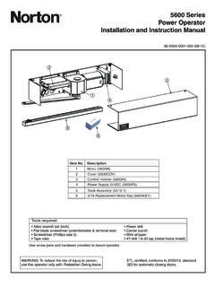
Transcription of *24213* 4040-SE Sentronic - mfsales.com
1 *24213*24213 This closer features two mounting options. Before beginning, determine which type of mounting best applies to your application, or had been specified for the job; then be sure to use the proper SentronicInstallation Instructions1 VoltageThe voltage shown on the track cover plate must match voltage supplied to door frame (24V or 120V). If concealed wiring is wanted, prepare the frame to specifications shown on the corresponding template (pull side or push side). If surface wiring is desired, be sure to mount track on frame before running any TrackingDepending on mounting used, insert proper track plugs into the side or top of the track. Using fasteners provided, mount track on frame to the dimensions of the template being used. Remove solenoid cover plate and make electrical connections (see pg.)
2 2). LNOTE: Switch hole in the cover plate MUST be aligned with the test/release switch when reattaching the plate to the Spring PowerBefore mounting closer, the spring power may need adjusting. Refer to the label on the closer spring tube. The 4040 SE comes preset at size 3. This will control a door up to 38 wide. If your door is wider than 38 , adjust closer as shown (see illustration to the right), up to 7 full turns. Starting the cover screws at this point is recommended. Using fasteners provided, mount the closer onto the door to the template dimensions being Arm InstallationPlace the arm spacer over the top shaft of the closer. Install the arm as follows:4a Push Side MountingPlace the arm hub over the top closer shaft, parallel with your door. Place a wrench on the bottom shaft of the closer, and rotate away from the door.
3 When flats in the arm hub line up with the first available flats of the shaft, slide the arm hub onto the shaft. Insert the shaft screw and tighten Pull Side MountingPlace the arm hub over the top closer shaft, parallel with the door. Rotate the arm away from the door until flats in the arm hub line up with first available flats of the shaft. Slide the arm hub onto the closer shaft. Insert the shaft screw and tighten Set Screw in ArmLoosen the set screw in the arm. Connect the art to the track roller, and tighten the set screw Adjusting Hold-Open Door PositionRemove the screw in the adjustable arm, and open the door to the desired position. Reinsert the screw and tighten RegulationDo not allow the door to slam into the frame. A normal closing time from a 90 position is 5 to 7 seconds, evenly divided between MAIN and LATCH SPEED.
4 If adjustments are needed, use a 3/32 hex wrench. To adjust the MAIN SPEED, turn regulating screw (see illustration below) clockwise to slow the speed or to increase the speed. LATCH SPEED is adjusted in the same way. When adjusting BACKCHECK, turn the regulating screw clockwise to increase the amount of force or to reduce the amount of force. LNOTE: Do not use an abrupt backcheck setting or expect the door closer to act as a stop!8 Door Closer CoverWith regulation done, place snap-on clip insert into the proper cutout, then snap the cover assembly onto the spring iNSTaLLaTiON OR REGULaTiON MaY RESULT iN PERSONaL iNJURY OR PROPERTY DaMaGE. FOLLOW aLL iNSTRUCTiON CaREFULLY. For questions, call LCN at Force=35 ft-lbs62 N48 N-mToIncreasePowerMainSpeedLatchSpeedBac kcheck HexWrenchNO MaiNTENaNCE REQUiRED WaRNiNGHaZaRDOUS VOLTaGE CaN SHOCK aND CaUSE SEVERE iNJURY!
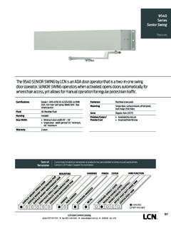
5 Disconnect the power before making any electrical connections or performing DIAGRAM - POLARITY NOT IMPORTANTINPUT VOLTAGE:24V AC/DC OR 120V AC/DC(usually from alarm panel or detector)HOLD-OPEN FORCEADJUSTMENT SCREWSOLENOIDASSEMBLYTERMINALLEADSGROUND TERMINALCONDUITHOLE PLUGRELEASETEST SWITCHTO EITHER TERMINALOPTIONAL SWITCHTO EITHER TERMINALPULLSIDEMOUNTINGPUSHSIDEMOUNTING TRACKPLUG(TOP) PLUG(SIDE)SE TRACKASSEMBLYTRACKROLLERARMSETSCREWARMSH AFTSCREWSE ARMASSEMBLY4040 SENTRONICCLOSER ASSEMBLYSNAP ONCLIP INSERT( or )SNAP ONCOVERNote: Use screws for metal cover : Use screws for metal cover DIAGRAM - POLARITY NOT IMPORTANTINPUT VOLTAGE:24V AC/DC OR 120V AC/DC(usually from alarm panel or detector)HOLD-OPEN FORCEADJUSTMENT SCREWSOLENOIDASSEMBLYTERMINALLEADSGROUND TERMINALCONDUITHOLE PLUGRELEASETEST SWITCHTO EITHER TERMINALOPTIONAL SWITCHTO EITHER TERMINALPUSHSIDEMOUNTINGTRACKSLIDETRACK PLUG(SIDE)SE TRACKASSEMBLYTRACKROLLERARMSETSCREWARMSH AFTSCREWSE ARMASSEMBLY4040 SENTRONICCLOSER ASSEMBLYNote: Use screws for metal cover (TOP) ONCLIP INSERT( or )SNAP ONCOVERNote: Use screws for metal cover Open Force adjustment: Locate the hold-open adjustment screw in the diagram above.
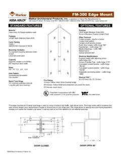
6 For greater hold-open force, insert a socket screw key wrencyh (included in the screwpack), and turn clockwise. To decrease the amount of hold-open force, turn the screw counter-clockwise. Turn a maximum of 4 checkout1. With power on, open the door complete. The door should remain in the open position. If the door does not stay open, Check the electrical Push the release test switch. The door should close immediately. Open the door to the hold-open position, and let it remain The system should be checked at frequent intervals. 4040Se Hinge Face MountedWaRNiNGHaZaRDOUS VOLTaGE CaN SHOCK aND CaUSE SEVERE iNJURY!Disconnect the power before making any electrical connections or performing for Right Hand DoorSeeNote 4 See Note 2 Hole for Electrical Connector ifConcealed Conduit Option Is Used21 2 111136426 1 DOOR HOLDER SOLENOID DATAT emplating for Left Hand Door24 VAC - DC Nominal =10% - 15% @.
7 090 - DC Nominal =10% - 15% @ .030 Amp. Note 2 DoorOptionalWiringConnectionsSee Note 485 to 110 Hold OpenAuxiliary Stop Recommended1 Hole for Electrical Connector ifConcealed Conduit Option Is Used 411112 621 1 4040SE } 3610222425272938 11 1 1 495773761021525526671 2 2 34621 26 Templating for Right Hand DoorSeeNote 4 See Note 2 Hole for Electrical Connector ifConcealed Conduit Option Is Used21 2 111136426 1 DOOR HOLDER SOLENOID DATAT emplating for Left Hand Door24 VAC - DC Nominal =10% - 15% @ .090 - DC Nominal =10% - 15% @ .030 Amp. Note 2 DoorOptionalWiringConnectionsSee Note 485 to 110 Hold OpenAuxiliary Stop Recommended1 Hole for Electrical Connector ifConcealed Conduit Option Is Used 411112 621 1 4040SE } 3610222425272938 11 1 1 495773761021525526671 2 2 34621 26 Notes:1.
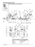
8 Voltage supplied to the unit MUST match the voltage shown on the Sentronic If the door is hung on pivots: Locate the closer and track from the pivot point of the center pivotj. For offset pivots: Locate from the pivot point and and add C\, . 3. The floor or wall stops should be If this dimension is greater than 1ZB\zn , consult the Reinforcing per ANSI/SDI-100 is recommended for hollow metal doors and If the swing clear hinges are being used, consult the \v>\znB\,11 Z\,1 Z\v1 ZZ\cx1 Z\x2 Z\,2 Z\v2 M\,34568 >\zn26 C\, Allegion 2014 Printed in Rev. 03/14-l4040SE Stop-Side MountedWaRNiNGHaZaRDOUS VOLTaGE CaN SHOCK aND CaUSE SEVERE iNJURY!Disconnect the power before making any electrical connections or performing for Right Hand DoorFace of Stopon Door SideDoorDoorStopHeaderJambLineOptionalWi ringConnectionsHinge Edgeof Doorof TrackCL*This dimension to be whenmounted on 1 wide stopDOOR HOLDER SOLENOID DATA24 VAC - DC Nominal =10% - 15% @.
9 090 - DC Nominal =10% - 15% @ .030 Amp. 2 1 1 Hole for Electrical ConnectorIf Concealed Conduit Option Is Used668 1 3 115326 *85 to 110 Hold OpenAuxiliary Stop Recommended4040SE }Templating for Left Hand DoorFace of Stopon Door SideDoorDoorStopJamb LineOptionalWiringConnectionsHingeEdgeof Doorof TrackCL*This dimension to be whenmounted on 1 wide stop2 2 1 1 Hole for Electrical ConnectorIf Concealed Conduit Option Is Used668 1 3 115326 *Templating for Right Hand DoorFace of Stopon Door SideDoorDoorStopHeaderJambLineOptionalWi ringConnectionsHinge Edgeof Doorof TrackCL*This dimension to be whenmounted on 1 wide stopDOOR HOLDER SOLENOID DATA24 VAC - DC Nominal =10% - 15% @ .090 - DC Nominal =10% - 15% @.
10 030 Amp. 2 1 1 Hole for Electrical ConnectorIf Concealed Conduit Option Is Used668 1 3 115326 *85 to 110 Hold OpenAuxiliary Stop Recommended4040SE }Templating for Left Hand DoorFace of Stopon Door SideDoorDoorStopJamb LineOptionalWiringConnectionsHingeEdgeof Doorof TrackCL*This dimension to be whenmounted on 1 wide stop2 2 1 1 Hole for Electrical ConnectorIf Concealed Conduit Option Is Used668 1 3 115326 *Notes:1. Voltage supplied to the unit MUST match the voltage shown on the Sentronic The Electrical connector is provided by LCN. 3. Locate the closer and track from the center line of the pivot or swing - clear the hing pin, if Floor or wall stops should be Reinforcing per ANSI/SDI-100 is recommended for hollow metal doors and \v>\znB\,11 Z\,1 Z\v1 ZZ\cx1 Z\x2 Z\,2 Z\v2 M\,34568 >\zn26 C\, Notes:Revision HistoryRevision Description:l > Revised artwork1.