Transcription of 5600 Series Power Operator Installation and …
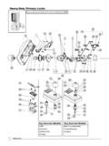
1 80-9356-0001-020 (08-12)5600 SeriesPower OperatorInstallation and Instruction manual Allen wrench set (inch) Power drill Flat blade screwdriver (potentiometer & terminal size) Center punch Screwdriver (Phillips size 2) Wire stripper Tape ruler #7 drill 1/4-20 tap (metal frame install)Tools required:Use screw pack and hardware provided to mount Operator . ETL certified; conforms to ANSI/UL standard325 for automatic closing doors. WARNING: To reduce the risk of injury to person, use this Operator only with: Pedestrian Swing Motor (5600M)2 Cover (5600 COV)3 Control Inverter (5600IN)4 Power Supply 24 VDC (5600PS)5 Track Assembly (5610-1)6 3/16 Replacement Motor Key (5600 KEY)26 ASSA ABLOY5431 For assistance, contact Norton Technical Product Support at is a registered trademark of Yale Security Inc.
2 , an ASSA ABLOY Group company. Copyright 2011, 2012 Yale Security Inc., an ASSA ABLOY Group company. All rights reserved. Reproduction in whole or in part without the express written permission of Yale Security Inc. is prohibited. 3000 Highway 74 East Monroe, NC 28112 Tel: (877)- Fax: (800) ABLOY80-9356-0001-020 ()08-1280-9356-0001-000 (04-13)WARNING: main Make sure that (120V, 60Hz) input Power is turned off at facility s circuit breaker before General Informationproceeding with Installation . Do not remove arm for : Your Low Energy Operator can be configured in three variations to meet the standards: 1. Push plates, Wave-to-open switches, etc. are available to activate the Operator . 2. Push & Go can be enabled. In this mode, your door is pushed (or pulled) 5 manually, and then automatically opens to full open position.
3 3. Door can be used as a manual door (Door Closer Mode). The door will work and act like a standard door closer, with Power , when pushed or pulled open manually. Push plates still active. If desired, overhead presence devices can be provided for an extra level of protection. Consult local authority having jurisdiction. These are not required by current ANSI/BHMA : When an opening signal is received by the control unit, the door opens to the fully open position. The open position is held by the motor. If the door is obstructed while opening, the door will stop; the Operator will sense obstruction and the door will close. Note: Door must be visible by person operating activation switch(es). Auxiliary door stop (by others) required. Closing: When the hold open time has elapsed, the Operator will close the door automatically, using the motor.
4 The door will slow to low speed at latch before it reaches the fully closed position. The door is kept closed by low Power . If the door is obstructed while closing, the door will stop; the Operator will sense obstruction, stop and stall. If obstructed more than two minutes, the unit will turn off. To reset, manually close the door, cycle Power and turn switch on. Activate push plates to test 3 !80-9356-0001-000 (04-13)Technical DataNotes: Input connections - torque to in/lbs (.55nm)Permanent wiring is to be employed as required by local codes. Activation devices: push plates, access control, mats, touchless wall switches, wire size is:12 AWG at terminals HOT and COM (120 VAC; 60Hz) on T1 Power Input at terminals 1 thru 4 on Accessory Terminal .120 VAC, amps24 V DC, max. " (81-91cm) 100-150 lb.
5 (45-68 kg)Input Power : Power consumption: Power supply:Door width*:Door weight:Door opening angle: Pull arm: 80 - 95 , with reveal 0 - 1/8" (0 - 3 mm)Hold open time:0-30 seconds ( 5 seconds min.)5 ampsCircuit breaker:*Interior Doors OnlyPage 4 Door PrepFasteners for Frame 1/4-20 Machine screws for hollow metal and aluminum. No. 14x2-3/4" (70mm) long sheet metal screws for : All dimensions are given in inches. Thickness recommended for reinforcements in hollow metal doors and frames is charted at the left of this page. Do not scale drawing. This template information based upon use of 5" maximum width butt hinges. Maximum frame reveal is 4" for this application. Before beginning the Installation , verify that the door frame is properly reinforced and is well anchored in the wall. Unreinforced hollow metal frames and aluminum frames should be prepared and fitted with 1/4-20 blind rivet nuts, furnished by others.
6 Concealed electrical conduit and concealed switch or sensor wires should be pulled to the frame before Metal Door Frame ReinforcingFrameMaterial12 ( )14 ( )16 ( )18 ( )12 ( )10 ( )10 ( )8 ( )18 ( )12 ( )12 ( )10 ( )ReinforcingRecommendedMin. Required1/8"(3)DoorFrameTemplating is based on 1/8" gap between door and frame. 80-9356-0001-000 (04-13)CLHinge2-1/2"2"Bottom of Frame1-1/4"1"6-5/8"11-3/8"16"15-1/2"Page 5 Operator MountingWARNINGDO NOT REMOVEARM FROM Operator !!WARNINGARM MUST CLEAR TOP OF DOOR. !1 Track Mounting3 Left hand door Using template, locate and prepare holes in the Drill #7 and tap 1/4-20 Machine Screws or Self Drilling Screws (6 places). Using template, locate and mount track. Track MUST be flush with top of Operator2 Attach Operator to frame using supplied page 11 for removable "CLScrew1 - Insert end caps2 - Attach screws3 - Snap on track cover80-9356-0001-000 (04-13)Page 6 Determine Hand of Door2 - ON = Push & Go OFF = Door Closer Mode1 - Door Mounting ON = RH OFF = LH Attach Arm45 Right HandLeft HandMagnets are used to signal the unit at closed and fully open positions.
7 With door in the closed position, slide Close Position Magnet so it aligns directly with the sensor. With door in the open position, slide Open Position Magnet so it aligns directly with the : Magnets must be adjusted to meet specific application needs. Latch and backcheck positions depend on magnet positions. Adjustment of Closed and Open Position6 AAttach arm to track slider using provided allen wrench. Turn screw PositionMagnetClose Position MagnetSensor80-9356-0001-000 (04-13)Page 7 See wiring diagram examples on pages Activation InputsRelay Outputs12347 Activation ConnectionDCF24 VDC Power Supply for Powered AccessoriesTerminalDescriptionHOTCOMC ommon Power lead (Neutral)Hot Power lead (120 VAC, 60Hz)Input Wiring instructions Grounding8!WARNINGUNIT WILL NOT FUNCTION CORRECTLY WITHOUT PROPER GROUNDINGGROUND WIRE MUST BE SECURED TO BACKPLATE UNDER HEAD OF (GREEN) GROUND SCREW LABELED GND.
8 CPower Connection9D24232225 HOTCOMB reakerSwitchFB80-9356-0001-000 (04-13)L2115YL1115/230 VAC INMOTOR OUTL2230 YUVWSTATUS LEDSPUSH PULLSW501 ONH/O TQH/O TMOBSTRSENSP1M/DLYP21216 COMSNSCOMPBK1K211 JMP503 NCNOTB501 EPage 81. Align Close Position Magnet with sensor. 2. Turn Power on at the Unit On/Off Switch located on the end Turn Breaker Switch to "Reset" (Breaker Switch shown in step 9). Red LED in breaker should be on and circuit board LEDs should Control Board Adjustments: Based on function adjustment desired, use table below to determine which POT is to be : Magnets must be adjusted for specific SHOCK RISK!(Adjustments made in the shaded area should be performed by Authorized Factory Personnel.)POTFUNCTIONDESCRIPTIONOBSTR SENS Obstruction Detection on OpenCW - IncreaseCCW - DecreaseM/DLYM otor Delay on OpeningCW - IncreaseCCW - DecreaseP1 Sweep Closing Force (90 - 20 )CW - IncreaseCCW - DecreaseH/O TMHold Open Time (5 - 30 Seconds)CW - IncreaseCCW - DecreaseP2 Latch Force (20 - 0) CW - IncreaseCCW - DecreaseH/O TQMotor Torque at Hold Open Backcheck PositionCW - IncreaseCCW - DecreaseEPower-On Procedures10 Control Set-Up11 ADJUSTMENT TABLES ignage12 Affix "Caution" Labels on both sides of the door.
9 Labels should be centered across the width of the door and 50" from the "Open PositionMagnetClose Position MagnetSensor80-9356-0001-000 (04-13)Page 9 Standard Function with SwitchesNotes:1. Power input to Door Operator Unit is at T1 Power Input Terminal (not shown) 120 VAC Switch, Card Reader, Key Switch, Open Momentary dry contactsWall Switch, Card Reader,Key Switch, Open Momentary dry contactsOperation: Doors are normally closed. Activating either switch will open both doors. Door will close after hold open time delay has 11234 Optional Door 2 Wave to Open Switch Wiring12341234 Wave to Open Switch(back side)Operation: Door is normally closed. Activating Wave to Open Switch will open the door. The door will close after hold open delay :1. Power input to Door Operator Unit is at T1 Power Input Terminal (not shown) 120 VAC Wave to Open Switch can be ordered separately or as a 24V Power SupplyFL N(AC)-V +VADJ+F80-9356-0001-000 (04-13)Fail Secure / Fail Safe Electric Strike WiringPage 10DC Electric Strike+-Wall Switch, Card Reader,Key Switch, Open Momentary dry contactsOperation: Door is normally closed and latched.
10 Activating switch will unlock the electric strike and the door will automatically open. Door will close after hold open time delay has elapsed. For Fail Secure Strike The door will remain during lockedpower failure. For Fail Safe Strike The door will remain unlockedduring Power SettingsPlace jumper to upper position for normally closed operation or to lower position for normally open Frequency Function Option12341234 Optional Door 212341234 Door 1 Notes:1. Power input to Door Operator Unit is at T1 Power Input Terminal (not shown) 120 VAC Radio Frequency Feature can be purchased as a separate : Door is normally closed. Activating wireless switch or hand held wireless transmitter will open the door. Door will close after hold open delay 24V Power Supply12345433 MHz Receiver(Mounted on Operator )Wiring for MomentaryHold Open FunctionFL N(AC)-V +VADJ+FL N(AC)-V +VADJ+FF80-9356-0001-000 (04-13)Page 11 Fail Safe Electromagnetic Lock 24 VDC Wiring24 VDC Electromagnetic Lock (Fail Safe)Operation: Door is normally closed and latched.