Transcription of 25 STEEL-CONCRETE COMPOSITE COLUMNS-I
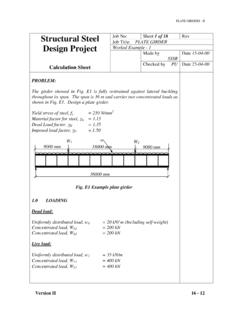
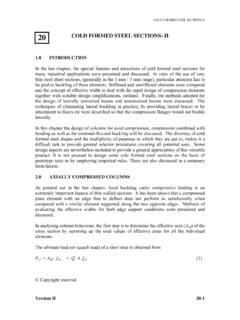
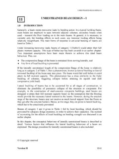
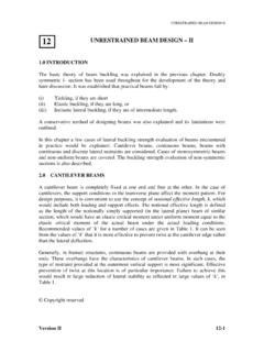
1 STEEL-CONCRETE COMPOSITE COLUMN-I Version II 25-1 Fig. 1: Typical cross - sections of fully and partially concrete encased columns cy cy x y h hc bc b cx cx (a) bc b h = hc x y ( c ) (b) h = hc x b = bc y STEEL-CONCRETE COMPOSITE COLUMNS-I INTRODUCTION A STEEL-CONCRETE COMPOSITE column is a compression member, comprising either a concrete encased hot-rolled steel section or a concrete filled tubular section of hot-rolled steel and is generally used as a load-bearing member in a COMPOSITE framed structure. Typical cross-sections of COMPOSITE columns with fully and partially concrete encased steel sections are illustrated in Fig. 1. Fig. 2 shows three typical cross-sections of concrete filled tubular sections.
2 Note that there is no requirement to provide additional reinforcing steel for COMPOSITE concrete filled tubular sections, except for requirements of fire resistance where appropriate. Copyright reserved 25 STEEL-CONCRETE COMPOSITE COLUMN-I Version II 25-2 Fig. 2: Typical cross-sections of concrete filled tubular sections d y x d y x b h y x In a COMPOSITE column both the steel and concrete would resist the external loading by interacting together by bond and friction. Supplementary reinforcement in the concrete encasement prevents excessive spalling of concrete both under normal load and fire conditions. In COMPOSITE construction, the bare steel sections support the initial construction loads, including the weight of structure during construction.
3 Concrete is later cast around the steel section, or filled inside the tubular sections. The concrete and steel are combined in such a fashion that the advantages of both the materials are utilised effectively in COMPOSITE column. The lighter weight and higher strength of steel permit the use of smaller and lighter foundations. The subsequent concrete addition enables the building frame to easily limit the sway and lateral deflections. With the use of COMPOSITE columns along with COMPOSITE decking and COMPOSITE beams it is possible to erect high rise structures in an extremely efficient manner. There is quite a vertical spread of construction activity carried out simultaneously at any one time, with numerous trades working simultaneously.
4 For example x One group of workers will be erecting the steel beams and columns for one or two storeys at the top of frame. x Two or three storeys below, another group of workers will be fixing the metal decking for the floors. x A few storeys below, another group will be concreting the floors. x As we go down the building, another group will be tying the column reinforcing bars in cages. x Yet another group below them will be fixing the formwork, placing the concrete into the column moulds etc. The advantages of COMPOSITE columns are: x increased strength for a given cross sectional dimension. x increased stiffness, leading to reduced slenderness and increased buckling resistance. x good fire resistance in the case of concrete encased columns.
5 X corrosion protection in encased columns. STEEL-CONCRETE COMPOSITE COLUMN-I Version II 25-3 x significant economic advantages over either pure structural steel or reinforced concrete alternatives. x identical cross sections with different load and moment resistances can be produced by varying steel thickness, the concrete strength and reinforcement. This allows the outer dimensions of a column to be held constant over a number of floors in a building, thus simplifying the construction and architectural detailing. x erection of high rise building in an extremely efficient manner. x formwork is not required for concrete filled tubular sections. MATERIALS Structural steel All structural steels used shall, before fabrication conform to IS: 1977-1975, IS: 2062-1992, and IS: 8500-1977 as appropriate.
6 Some of the structural steel grade commonly used in construction as per IS: 961-1975 and IS: 1977-1975 are given in Table 1. Table1(a): Yield strength fy of steel sections Nominal steel grade Nominal thickness/diameter (mm) Yield stress, fy (MPa) t 6 350 6d t d28 350 Fe 570-HT 28 t d 45 340 t 6 350 6d t d16 350 Fe 540W-HT 16 t d32 340 t 6 250 6d t d20 250 Fe 410-O (not subjected to dynamic loading other than wind) 20 t d40 240 Table1(b): Yield strength fy of steel sections as per IS 2062:1992 Nominal steel grade Nominal thickness/diameter (mm) Yield stress, fy (MPa) < 20 250 20 - 40 240 Fe 410W A > 40 230 < 20 250 20 - 40 240 Fe 410W B > 40 230 < 20 250 20 - 40 240 Fe 410W C > 40 230 STEEL-CONCRETE COMPOSITE COLUMN-I Version II 25-4 Concrete Concrete strengths are specified in terms of the characteristic cube strengths, (fck)cu, measured at 28 days.
7 Table 2 gives the properties of different grades of concrete according to IS: 456-2000 and the corresponding EC4 values. Table 2: Properties of concrete Grade Designation M25 M30 M35 M40 (fck)cu (N/mm2) 25 30 35 40 (fck)cy (N/mm2) 20 25 28 32 fctm(N/mm2) Ecm=5700 (fck)cu(N/mm2) 28500 31220 33720 36050 where, (fck)cu characteristic compressive (cube) strength of concrete (fck)cy characteristic compressive (cylinder) strength of concrete, given by times 28 days cube strength of concrete according to EC4 fctm mean tensile strength of concrete For lightweight concrete, the Ecm values are obtained by multiplying the values from Table 2 by U /2400,where U is the unit mass (kg/m3)
8 Reinforcing steel steel grades commonly used in construction are given in Table 3. It should be noted that although the ductility of reinforcing bars has a significant effect on the behaviour of continuous COMPOSITE beams, this property has little effect on the design of COMPOSITE columns. Concrete filled tubular sections may be used without any reinforcement except for reasons of fire resistance, where appropriate. Table 3: Characteristic strengths of reinforcing steel Type of steel Indian Standard Nominal size (mm) Yield Stress, fsk (N/mm2) dd20 250 Mild steel Grade I (plain bars) IS:432(Part1)-1982 20<dd50 240 dd20 225 Mild steel Grade II (plain bars) IS:432(Part1)-1982 20<dd50 215 dd16 540 16<dd32 540 Medium tensile steel (plain bars) IS:432(Part1)-1982 32<dd50 510 415 500 Medium tensile steel (Hot-rolled deformed bars and Cold-twisted deformed bars) IS:1786-1985 for bars of all sizes 550 STEEL-CONCRETE COMPOSITE COLUMN-I Version II 25-5 Note.
9 This chapter is confined to steel concrete COMPOSITE columns made up of hot rolled steel sections having yield strengths within the range 250 N/mm2 to 350 N/mm2 and reinforcement with steel rods of 415 or 500 N/mm2. This limitation is considered necessary at the present time on account of the lower ductility of steels having higher yield strengths. Partial safety factors Partial safety factor Jf for loads - The suggested partial safety factor Jf for different load combinations is given below in Table 4. Table 4 : Partial safety factors ( According to proposed revisions to IS 800) Jf Loading DL LL WL Dead Load (unfavourable effects) - - Dead load restraining uplift or overturning - - Imposed Load + Dead Load - Dead Load + Wind Load - Dead Load + Imposed Load + wind Load (Major Load) Dead Load + Imposed Load (Major Load) + wind Load Partial safety factor for materials The partial safety factor Jm for structural steel , concrete and reinforcing steel is given in Table5.
10 Table 5: Partial safety factor for materials Material Jm* steel Section Concrete Reinforcement *IS: 11384-1985 Code for COMPOSITE construction has prescribed Jm = for structural steel . (By contrast, EC4 has prescribed Jm = for structural steel ). COMPOSITE COLUMN DESIGN General As in other structural components, a COMPOSITE column must also be designed for the Ultimate Limit State. For structural adequacy, the internal forces and moments resulting from the most unfavourable load combination should not exceed the design resistance of STEEL-CONCRETE COMPOSITE COLUMN-I Version II 25-6 the COMPOSITE cross-sections. While local buckling of the steel sections may be eliminated, the reduction in the compression resistance of the COMPOSITE column due to overall buckling should definitely be allowed for, together with the effects of residual stresses and initial imperfections.