Transcription of 327590-101 REV. B - dms.hvacpartners.com
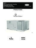
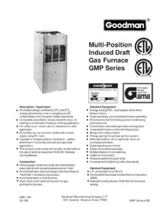
1 Form No. PDS MultipoiseInduced CombustionGas Furnace310 AAV/310 JAVS izes 045 thru 155 Series A A02182 The 310 AAV/310 JAV 4-Way Multipoise Gas Furnace was designed by Bryant dealers for Bryant dealers. Applications are easy with 4-way multipoise design, through-the-furnace downflow venting, 13 dif ferent venting options, and a door designed for easy service access. An inner blower door is provided for tighter sealing in sensitive applications. The 310 AAV/310 JAV furnace is approved for use with natural or propane gas, and the 310 JAV is approved for use in Low NOx Air Quality Management FEATURES.
2 Noise elimination combustion system. Microprocessor based control center Adjustable heating air temperature rise LED diagnostics and self test feature. Patented blocked vent safeguard to ensure proper furnace venting . All models are Chimney Friendly when used with accessory vent kit . Four-position furnace: upflow, horizontal right, horizontal left, downflow Thirteen different vent options. Shorter in height, only 331/3" tall. Heat pump compatible. Hot surface Ignition (HSI). Residential installations eligible for consumer financing through the Comfort Credit Program.
3 Twinning in Upflow, Downflow, and Horizontal LIMITED WARRANTY. 20-year warranty on "Super STM" heat exchanger. 5-year parts warranty on all other components-2-MEETS DOE RESIDENTIAL CONSERVATIONSERVICES PROGRAM purchasing this appliance, read importantenergy cost and efficiency information availablefrom your Two additional 7/8-in. dia knockouts are located in the top Minimum return-air openings at furnace, based on metal duct. If flex duct is used, see flex duct manufacturer's recommendations for equivalent Minimum return-air opening at furnace: a.
4 For 800 CFM-16-in. round or 141/2 x 12-in. rectangle. b. For 1200 CFM-20-in. round or 14 x 19-in. rectangle. c. For 1600 CFM-22-in. round or 14 x 22-in. rectangle. d. For airflow requirements above 1800 CFM, see Air Delivery table in Product Data literature for specific use of single side inlets. The use of both side inlets, a combination of 1 side and the bottom, or the bottom only will ensure adequate return air openings for airflow requirements above 1800 :1/21/21/21/16R E G I ST E R E D QU A L I T Y SY ST E MCarrierCorporationREGISTEREDFIRMISO9001 #A2883 EFFICIENCYRATINGCERTIFIEDCERTIFIED1) 135 and 155 size furnaces require five-inch vents.
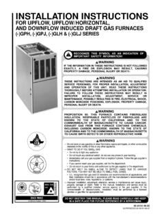
5 Use a 4-5 inch vent adapter between furnace and vent stack. 2) See Installation Instructions for complete installation UNIT SIZE A (CABINET WIDTH) D (SUPPLY WIDTH) E (BOTTOM RETURN WIDTH) VENT CONNECTION SIZE (see notes 1 & 2) 14-3/16 12-9/16 12-11/16 9-5/16 4 14-3/16 12-9/16 12-11/16 9-5/16 4 14-3/16 12-9/16 12-11/16 9-5/16 4 14-3/16 12-9/16 12-11/16 9-5/16 4 17-1/2 15-7/8 16-1/8 11-9/16 4 17-1/2 15-7/8 16-1/8 11-9/16 4 21 19-3/8 19-1/2 13-5/16 4 21 19-3/8 19-1/2 13-5/16 4 17-1/2 15-7/8 16-1/8 11-9/16 4 21 19-3/8 19-1/2 13-5/16 4 21 19-3/8 19-1/2 13-5/16 4 21 19-3/8 19-1/2 13-5/16 4 (note 1)
6 024045 24-1/2 22-7/8 23 15-1/16 4 (note 1) 24-1/2 22-7/8 23 15-1/16 4 (note 1) 0600900480900420900480700360700240700360 45066110048110036110066135048135060155 SHIPPINGWEIGHT10410711111512612714014613 5146152149163170F( TOP &VENT OUTLET) BOTTOM28-7/8"25-1/4"22-9/16"JUNCTION BOXLOCATION7/8" DIAACCESSORY1/2" DIA THERMOSTATWIRE ENTRY3-15/16"LEFT HAND GAS ENTRY33-5/16"24-7/8"5-1/2"7/8" DIA. ACCESSORY11/16"21-5/8"BOTTOM INLET1-11/16"13/16"11/16"1-9/16"2-9/16"4 -13/16"AIRFLOW19"OUTLET13/16"11/16"8-7/1 6"1-7/16"ALTERNATEJUNCTION BOXLOCATION (TYP)VENT OUTLET5 PLACES (TYP)3-3/4"1-1/2" HAND GAS ENTRY1/2" DIA.
7 THERMOSTATWIRE ENTRYSIDE INLET14-7/8"7/8" DIA. ACCESSORY1-1/4"1"22-1/16"ADFE26-1/8"(VEN T CONNECTION)24"(CASING) CONTROLS-THERMOSTATS AND ZONINGTHERMOSTAT- NON-PROGRAMMABLEAuto Changeover, oF/oC, 1-Stage Heat/1-Stage Cool - TSTATBBNAC01-BAuto Changeover, oF/oC, 2-Stage Heat/1-Stage Cool - TSTATBBNHP01-BAuto Changeover, oF/oC, 2-Stage Heat/2-Stage Cool - TSTATBBN2S01-Bin AC Mode, 3-Stage Heat/2-Stage Cool in HP ModeAir Conditioner, 1-Stage Heat/1-Stage Cool, Manual Changeover, oF/oC - TSTATBBBAC01 Heat Pump, 2-Stage Heat/1-Stage Cool, Manual Changeover, oF/oC - TSTATBBBHP01*THERMOSTAT- PROGRAMMABLEAuto Changeover, 7-Day Programmable, oF/oC.
8 1-Stage Heat/1-Stage Cool - TSTATBBPAC01-BAuto Changeover, 7-Day Programmable, oF/oC, 2-Stage Heat/1-Stage Cool - TSTATBBPHP01-BAuto Changeover, 7-Day Programmable, oF/oC, 2-Stage Heat/2-Stage Cool - TSTATBBP2S01-Bin AC Mode, 3-Stage Heat/2-Stage Cool in HP ModeDual Fuel Thermostat, includes Outdoor Air Temperature Sensor - TSTATBBPDF01-B*Thermidistat Control - Non-Programmable/Programmable Thermostat - TSTATBBPRH01-B*with Humidity Control (For use in Dual Fuel, AC, HP, and 2S applications. Includes Outdoor AirTemperature Sensor.)ZONING- 2-ZONEZONEBB2 KIT01-B, ZONEKIT2 ZBDPZONING- 4-ZONEZONEBB4 KIT01-BZONING- 8-ZONEZONEBB8 KIT01-B* Do not use in zoning heat pump INCHES CLEARANCE TO COMBUSTIBLE CONSTRUCTIONC ette fournaise air puls est quip e pour utilisation avec gaz naturel et altitudes comprises entre 0-3,050m (0-10,000 pi).
9 Utiliser une trousse de conversion, fournie par le fabricant, pour passer au gaz propane ou pour certaines installations au gaz fournaise est pr vue pour tre install e dans un b timent construit sur fournaise peut tre install e sur un plancher combustible dans une alc ve ou dans un garde-robe en respectant le minimumd'espace libre des mat riaux combustibles, tel qu'indiqu sur le fournaise peut tre utilis e avec un conduit d vacuation de Type B-1 ou connect e au conduit commun d autres appareils MINIMALE EN POUCES AUX CONSTRUCTIONS COMBUSTIBLES INSTALLATION327590-101 REV.
10 BMINIMUM INCHES CLEARANCE TO COMBUSTIBLE CONSTRUCTIOND GAGEMENT MINIMUM EN POUCES AVEC L MENTS DE CONSTRUCTION COMBUSTIBLES *Installation on non-combustible floors only. For Installation on combustible flooring only when installed on special base, Part No. KGASB0201 ALL, Coil Assembly, Part No. CD5 or CK5, or Coil Casing, Part No. inches front clearance required for supply or return sides when furnace is in the horizontal position. Line contact only permissible between lines formed by intersections of the Top and two Sides of the furnace jacket, and building joists, studs or in inches D gagement (po).