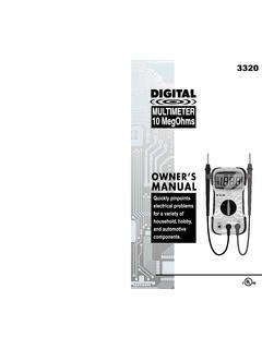
Transcription of 3300 Multimeter English SinglePage New
1 SAFETY PRECAUTIONS/WARNINGS This Digital Multimeter is intended for INDOOR USE ONLY. Pay close attention to WARNINGS stamped on the front and rear of themeter's case. These warnings, as well as all warnings and precautions usedthrough out this manual, must be followed to avoid electric shock and/or per-sonal injury. The RESPONSIBLE PARTY shall be made aware that, if the equipment isused in a manner not specified by the manufacturer, the protection providedby the equipment may be prevent electrical shock and/or damage to the tester or the equipment undertest, observe the following safety precautions: DO NOT apply more than the rated voltage, as marked on the meter,between terminals or between any terminal and earth ground. Use caution when working above 30V AC rms, 42 V peak, or 60 V DC. Suchvoltages pose a shock hazard. To avoid false readings that could lead to possible electric shock or personalinjury, replace the batteries as soon as the low battery indicator displays.
2 Use ONLY those test leads or probes provided with the meter. DO NOT use third-party test leads or probes. Always inspect the Multimeter , test leads and any other accessories for dam-age prior to every use. If any damage is found, do notuse tester until repairsare done. Always consider electrical and electronic equipment to be ener-gized (live).Never assume any equipment is de-energized. Never ground yourself when taking electrical measurements. Isolate yourselffrom ground by using dry rubber insulating mats to cover all exposed/ground-ed metal. Stand on rubber mats and wear dry SPECIFICATIONS AND FEATURES 3- digit LCD display (maximum reading of 2000) Manual range control Automatic negative (-) polarity indication Automatic zero adjustment Over range indicator (except 10 A function). Displays "1" on LCD Low battery indicator. Displays battery symbol on LCD Safety standard:CE EMC/LVD.
3 The meter is up to the standards of IEC1010 Pollution Degree 2, over voltage Category 2 (signifies protection againsttransient impulses at the local level mains electrical supply). Equipment marked is protected throughout by Double or Reinforced Insulation. Operating environment:Temperature - 32 to 104 F. (0 C to 40 C)Humidity - Less than 80% relative humidity (non-condensing)Altitude - up to 6562 ft (2000 meters) Storage environment:Temperature - 4 to 140 F (- 20 to 60 C)Humidity - Less than 90% relative humidity (non-condensing) Power Supply: One 9-volt (6F22) battery Fuse: 315mA/250V 5X20 mm (Radio Shack, GMA/217 series ; #270-1046)fuse Dimensions:Height - in. (139 mm)Width - in. (89 mm)Depth - in. (32 mm) Weight (including batteries): approximately oz (170 g)ELECTRICAL SPECIFICATIONSA ccuracy of specifications in the following tables are based on an operatingtemperature of 64 F to 82 F (18 C to 28 C) and a relative humidity of less than75%.
4 Maximum voltage from V masocket to COMsocket is 500V AC/DC; from COMsocket to ground is 300V VOLTSRESISTANCE (OHMS)DIODE TESTDC AMPSBATTERY TESTAC VOLTSTESTING PROCEDURESA. AC/DC VOLTAGE MEASUREMENTR angeResolutionAccuracyOverloadProtection 200 (1% of reading 2K 1 + 5 digits)250V DC/AC RMS20K 10 200K 100 20M 10K (2% of reading + 5 digits)Open Circuit Voltage:Approximately 3 VFunctionRange ResolutionAccuracyOverloadProtectionDiod e ~ Circuit Voltage:Approximately Voltage Drop:Approximately 1mARangeResolutionAccuracyOverloadProtec tion2000 A1 A20mA10 A ( of fuse200mA100 A+ 5 digits)10A10mA (2% of reading Non-Protected+ 5 digits)Measuring time is equal to or less than 15 seconds and timeinterval is equal to or over 15 fuse9 VOverloadRangeResolutionAccuracyProtecti on200V100mV ( of reading 500V DC or AC500V1V+ 10 digits)Frequency:40-400 HzOWNER S MANUALDIGITAL MULTIMETERMRP #93-0187 Rev.
5 ARangeResolutionAccuracyOverload Protection200mV100 V230 Vrms2V1mV ( of reading20V10mV+ 5 digits)500V DC200V100mVor AC500V1V ( of reading+ 5 digitsInput impedance:10M for all 1 -- 2 -WARNING To avoid possible electric shock, instrument damage and/or equipmentdamage, DO NOT attempt to measure voltages ABOVE 500V AC/DC ortake measurements if the voltage is unknown. 500V AC/DC between theCOM and V jacks is the maximum voltage that this instrument isdesigned to measure. The "COM" terminal potential should not exceed300V AC/DC measured to the BLACK test lead into "COM" jack of the Multimeter ; plug the REDtest lead into the "V" the meter s Function/Range Selector Switch to the appropriate ACV orDCV position as the RED test lead onto the positive (+) side of the item being testedand the BLACK test lead onto the negative (-) (across the source/load) sideof the CAREFULnot totouch any energized conductors with anypart of your the results on the RESISTANCE MEASUREMENT (OHMS) the RED test lead into the " " jack of the Multimeter ; plug the BLACK test lead into the "COM" the meter s Function/Range Selector Switch to the OHM " " the RED test lead onto one side of the item being tested and theBLACK test lead onto the other side of the item.)
6 (Polarity does not matterwhen checking resistance). the results on the DIODE the RED test lead into the jack of the Multimeter ; plug the BLACK test lead into the "COM" the meter s Function/Range Selector Switch to the the RED test lead onto one side of the diode being tested and theBLACK test lead onto the other the results on the the test leads and again read the results on the display. Comparethe two readings. One reading should indicate a voltage drop value; theother reading should indicate an overrange (1) DC CURRENT MEASUREMENT (AMPS) the RED test lead into the "mA" or the "DC10A" jack of the multime-ter, as applicable; plug the BLACK test lead to the "COM" the meter's Function/Range Selector Switch to the appropriate Ampsrange position as desired. To measure from 0 to 200mA, set the Selector Switch to the desired"DCmA" position.
7 To measure from 200mA to 10 Amps DC, set the Selector Switch to the"DC10A" the battery, or shut off the power to the circuit being one end of the wire or device, from the circuit where current willbe the RED test lead on the disconnected wire and place the BLACK test lead at the location from which the wire was disconnected ( series con-nection). the battery, or apply power to the circuit being the results on the : After the test is completed, shut the power off to the circuitbefore removing the test leads and before reconnecting any disconnectedwires or BATTERY the RED test lead into the "BAT." jack of the Multimeter ; plugtheBLACK test lead into the "COM" the voltage rating of the battery to be the meter s Function/Range Selector Switch to the desired "BatteryTest" the RED test lead on the positive post of the battery under test; placethe BLACK lead on the negative the results on the periodic maintenance is required other than the replacement of the battery,the fuse, and visual inspection of the the meter clean and dry.
8 DO NOT use solvent to clean, use a damp(not wet) cloth and fully dry after AND FUSE the Digital Multimeter OFF and remove the test the two screws on the back of the meter and separate the the fuse or battery as necessary: For battery replacement:Remove the battery from the battery com-partment and replace onlywith one 9-volt alkaline battery. For fuse replacement:Remove the fuse from the fuse holder andreplace with a - UL Listed Bussmann, GMA Type(Radio Shack GMA/270 series ; #270-1046 ) :Use a , 5x20mm type fuse ONLY - Bussmann, GMA Type(Radio Shack #270-1046 or similar). Using an incorrect fuse may result in seri-ous injury and/or damage to the the case and secure with the two ONE YEAR WARRANTYThe Manufacturer warrants to the original purchaser that this unit is free ofdefects in materials and workmanship under normal use and maintenance fora period of one (1) year from the date of original purchase.
9 If the unit fails with-in the one (1) year period, it will be repaired or replaced, at the Manufacturer soption, at no charge, when returned prepaid to the Service Center with Proofof Purchase. The sales receipt may be used for this purpose. Installation laboris not covered under this warranty. All replacement parts, whether new orremanufactured, assume as their warranty period only the remaining time ofthis warranty. This warranty does not apply to damage caused by improperuse, accident, abuse, improper voltage, service, fire, flood, lightning, or otheracts of God, or if the product was altered or repaired by anyone other than theManufacturer s Service Center. The Manufacturer, under no circumstancesshall be liable for any consequential damages for breach of any written war-ranty of this unit. This warranty gives you specific legal rights, and you mayalso have rights, which vary from state to state.
10 This manual is copyrighted withall rights reserved. No portion of this document may be copied or reproducedby any means without the express written permission of the WARRANTY IS NOT TRANSFERABLE. For service, send via (ifpossible) prepaid to Manufacturer. Allow 3-4 weeks for PROCEDURESIf you have any questions, require technical support or information onUPDATES and OPTIONAL ACCESSORIES, please contact your local store,distributor or the Service & Canada:Technical Service Center17352 Von Karman , CA 92614 (800) 544-4124 (6:00 AM-6:00 PM, 7 days a week PST)All others:(714) 241-6802 (6:00 AM-6:00 PM, 7 days a week PST)FAX:(714) 432-3979 (24 hr.) 3 -- 4 -Copyright 2013 IEC. All Rights Resistance measurements must be made on "de-energized" (dead) cir-cuits ONLY. Impressing a voltage across the Multimeter 's terminals whileset to any resistance range may result in electric shock, instrument dam-age and/or damage to equipment under test.
