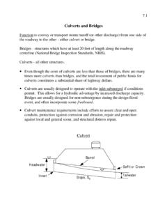
Transcription of 4.5 Culvert Construction 4.5.1 General
1 Culvert Repair, Materials, and Structural Design 2000 ConnDOT Drainage Culvert are two major classes of Culvert installations, based upon the conditions that influenceloads: 1) trenched, where culverts are placed in natural ground or compacted fill with acontrolled trench width and 2) embankments, where culverts are usually placed in natural groundbut are covered by a constructed embankment. A third method of installation for placing culvertsis boring and jacking, used where deep installations are necessary or where conventional openexcavation is not practical. TrenchedTrench installations are made in relatively narrow excavations on a carefully prepared beddingto distribute the load and the Culvert is covered with earth backfill that extends to the groundsurface.
2 The trench load theory is based on the following assumptions: Earth loads on the pipe develop as the backfill settles. The resulting earth load on the pipe is equal to the weight of the material above the top ofthe pipe minus the shearing (frictional) forces on the side of the trench. Cohesion is negligible because, with cohesive soils, considerable time must elapse beforeeffective cohesion between the backfill material and the sides of the trench can develop,and with cohesionless soils, would never develop. The assumption of no cohesion yieldsthe maximum probable load on the pipe. For a rigid pipe, the side fills may be relatively compressible and the pipe will carry a largeportion of the load over the entire width of the trench. For rigid pipe, active lateral pressure is neglected, which, in effect, increases the requiredpipe strength.
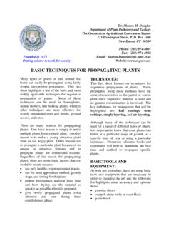
3 (However, it should be taken into, account if investigations and experienceindicate such pressure is flexible culverts, a well-compacted soil envelope of adequate width is needed to developthe lateral pressures required to maintain the shape of the Culvert . The width is a function of thestrength of the surrounding in-situ soil and the size of the backfill load ultimately transmitted to the pipe is a function of the trench width. With rigidculvert placement, the determination of the backfill load is based on the trench width and a pipestrength is selected to withstand that load. If the actual trench width exceeds the width assumedin design, the load on the Culvert will be greater than estimated and structural distress Culvert Repair, Materials, and Structural DesignConnDOT Drainage ManualOctober 2000 Figure 4-13 illustrates the load carried by a rigid Culvert installed in a normal trench 4-13 Trench installationFigure 4-14 illustrates the increased load on the rigid Culvert if the width of the trench 4-14 Wide trench installationIf an excessively wide trench is excavated or if the sides are sloped back, the Culvert can beinstalled in a narrow subtrench excavated at the bottom of the wider trench, as shown in Figure4-15, to avoid an increase in the backfill Repair, Materials.)
4 And Structural Design 2000 ConnDOT Drainage ManualFigure 4-15 Subtrench installation in a wide trench Bedding - A stable and uniform foundation is necessary for the satisfactory performanceof any Culvert . Once a stable and uniform foundation is provided, the bedding should be preparedin accordance with the plans and bedding preparation is critical to both structural performance and service life. Animportant function of the bedding is to provide uniform support along the barrel of each pipesection. The bed should be placed to uniform grade and line to ensure good vertical alignmentand to avoid excessive stresses at joints. The bed material should be free of rock formations,protruding stones, frozen lumps, roots, and other foreign matter that may cause unequalsettlement.
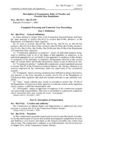
5 When a corrugated metal Culvert is being placed, the corrugations should be firmlyseated in the foundation or circumferential cracks in rigid pipe may be caused by poor bedding. Cracks canoccur across the bottom of the pipe (broken belly) when the pipe is only supported at the ends ofeach section. This is generally the result of poor installation practices such as not providingindentions (bell holes) in hard foundation material for the ends of bell and spigot-type pipe or notproviding a sufficient depth of suitable bedding material. Cracks may occur across the top ofpipe (broken back) when settlement occurs and rocks or other areas of hard foundation materialnear the midpoint of a pipe section are not adequately covered with suitable bedding cracking is illustrated in Figure bedding distributes the load reaction around the lower periphery of the pipe.
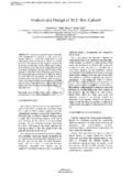
6 The requiredsupporting strength of the pipe is directly related to this load distribution. Pipe set on a flatfoundation without bedding results in high load, concentration at the bottom of the pipe and islikely to result in shear cracking of the pipe at the five o clock and seven o'clock 4-17 illustrates how the distribution of the bedding over increasing percentages of theoutside diameter can increase the supporting strength of the Culvert . Any time a pipe is installedon a flat-bottom foundation, it is essential that the bedding material be uniformly compactedunder the haunches of the Culvert Repair, Materials, and Structural DesignConnDOT Drainage ManualOctober 2000 Properly prepared bedding evenly distributes prepared bedding may result in stress prepared 4-16 Transverse or circumferential cracks Backfilling - The backfill is made up of two areas that may require different material andseparate compaction criteria.
7 The first area extends from the bedding to approximately 300 mm(12 inches) above the Culvert . The second area includes the remaining load-carrying capacity of an installed Culvert depends largely on the initial backfillingaround the Culvert . Since proper compaction of backfill material is so important, material anddensity criteria is often included in the bedding trench installations, where space is limited, tamping by pneumatic or mechanical impacttampers is usually the most effective means of compaction. Impact tampers are most effective forclay soils while granular soils are consolidated best by vibration. Backfill material should beplaced in layers not exceeding 150 mm (6 inches) deep, deposited alternately on opposite sidesof the Repair, Materials, and Structural Design 2000 ConnDOT Drainage ManualFigure 4-17 Correlation of bedding and supporting strength for rigid Culvert Repair, Materials, and Structural DesignConnDOT Drainage ManualOctober 2000 EmbankmentsCulverts placed in an embankment are usually bedded in natural ground and are overlaid by aconstructed embankment.
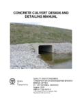
8 The required supporting strength of a buried pipe is determined by thetotal load that is imposed upon the pipe. The magnitude of the load is influenced by theuniformity and stability of the support soil, as well as conditions around and over the , the load-carrying capability of rigid culverts is essentially carried by the structuralstrength of the pipe itself since rigid pipe is stiffer than the surrounding soil. A well-compactedsoil envelope is required to develop the lateral pressures necessary to maintain the shape offlexible installations can be divided into three groups: positive projection, negativeprojection, and induced trench. The essential features of these types of installations are shown inFigure 4-18. Refer to ConnDOT Standard Sheets and Standard Specifications for trench andembankment pipe 4-18 Essential features of various types of installationPositive projection pipe is installed with the top of the pipe projecting above the surface of thenatural ground, or compacted fill, and then covered with earth fill.
9 Negative projection pipe ininstalled in relatively shallow trenches so that the top of the pipe is below the level of the naturalground or compacted fill. It is then covered with earth fill to the required depth. The inducedtrench pipe is usually installed as positive projection. However, when the fill has been placed to adepth of at least one pipe diameter over the proposed top of the pipe, a trench is excavated overthe pipe and backfilled with a more compressible Repair, Materials, and Structural Design 2000 ConnDOT Drainage Manual Bored, Augured or JackedThe process of tunneling and jacking pipe culverts is used where deep installations arenecessary or where conventional open excavation and backfill methods may not be usual procedure in jacking pipe is to equip the leading edge with a cutter, or shoe, toprotect the pipe.
10 As succeeding lengths of pipe are added between the lead pipe and the jacks,and the pipe is jacked forward, soil is excavated and removed through the pipe. Material istrimmed so that the bore size slightly exceeds the outside diameter of the pipe and excavationdoes not precede the jacking operation more than is necessary. Such a procedure usually resultsin minimum disturbance to the natural soils adjacent to the pipe. A minimum 36 diameter isusually required for conventional jacking operations. A typical installation for jacking Pipe isshown in Figure 4-19 Typical jacking installationA lubricant, such as a bentonite slurry, is sometimes pumped into the space between thetunnel bore and the outside of the pipe to reduce the frictional resistance. After the jacked pipehas reached its final position, grout is frequently pumped into the same space to, ensurecontinuous bearing with the surrounding types of loads are imposed upon concrete pipe installed by the jacking method: the axialload due to the jacking pressures applied during installation; and the earth loading due to theoverburden, with some possible influence from live loadings, which generally become effectiveonly after installation is Culvert Repair, Materials, and Structural DesignConnDOT Drainage ManualOctober 2000 There are several advantages to jacking pipe: Traffic is not interrupted on the overlying roadway.