Transcription of FHWA - CULVERT DESIGN - Civil Engineering …
1 fhwa - CULVERT DESIGN . Outlet control flow conditions can be calculated based on energy balance. The total energy (HL). required to pass the flow through the CULVERT barrel is made up of the entrance loss (He), the friction losses through the barrel (Hf), and the exit loss (Ho). Other losses, including bend losses (Hb), losses at junctions (Hj), and loses at grates (Hg) should be included as appropriate. These losses are discussed in Chapter 6. HL = H e + H f + H o + H b + H j + H g (1). The barrel velocity is calculated as follows: Q. V= (2). A. V is the average velocity in the CULVERT barrel, m/s (ft/s). Q is the flow rate, m3/s (ft3/s). A is the full cross sectional area of the flow, m2 (ft2).
2 The velocity head is: V2. HV = (3). 2g g is the acceleration due to gravity, m/s/s ( ft/s/s). The entrance loss is a function of the velocity head in the barrel, and can be expressed as a coefficient times the velocity head. V2 . H e = k e (4a). 2g . Values of ke based on various inlet configurations are given in Table 12, Appendix D. The friction loss in the barrel is also a function of the velocity head. Based on the Manning equation, the friction loss is: K n2 L V 2. H f = U (4b). R 2g KU is (29 in English Units). n is the Manning roughness coefficient (Table 4). L is the length of the CULVERT barrel, m (ft). R is the hydraulic radius of the full CULVERT barrel = A/p, m (ft).
3 A is the cross-sectional area of the barrel, m m2 (ft2). p is the perimeter of the barrel, m (ft). V is the velocity in the barrel, m/s (ft/s). The exit loss is a function of the change in velocity at the outlet of the CULVERT barrel. For a sudden expansion such as an endwall, the exit loss is: 34. fhwa - CULVERT DESIGN . fhwa - CULVERT DESIGN . V 2 Vd2 . H o = (4c). 2g 2g . Vd is the channel velocity downstream of the CULVERT , m/s (ft/s). Equation (4c) may overestimate exit losses, and a multiplier of less than can be used. (40). The downstream velocity is usually neglected, in which case the exit loss is equal to the full flow velocity head in the barrel, as shown in Equation (4d).
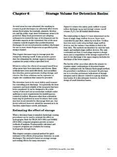
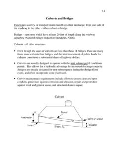
4 V2. Ho = H v = (4d). 2g Bend losses, junction losses, grate losses and other losses are discussed in Chapter VI. These other losses are added to the total losses using Equation (1). Inserting the above relationships for entrance loss, friction loss, and exit loss (Equation 4d) into Equation (1), the following equation for loss is obtained: K n2 L V 2. H = 1 + k e + U (5). R 2g Figure III-8--Full Flow Energy and Hydraulic Grade Lines Figure III-8 depicts the energy grade line and the hydraulic grade line for full flow in a CULVERT barrel. The energy grade line represents the total energy at any point along the CULVERT barrel. HW is the depth from the inlet invert to the energy grade line.
5 The hydraulic grade line is the depth to which water would rise in vertical tubes connected to the sides of the CULVERT barrel. In full flow, the energy grade line and the hydraulic grade line are parallel straight lines separated by the velocity head lines except in the vicinity of the inlet where the flow passes through a contraction. The headwater and tailwater conditions as well as the entrance, friction, and exit losses are also shown in Figure III-8. Equating the total energy at sections 1 and 2, upstream and downstream of the CULVERT barrel in Figure III-8, the following relationship results: 35. fhwa - CULVERT DESIGN . fhwa - CULVERT DESIGN .
6 Vu2 Vd2. HWo + = TW + + HL (6). 2g 2g HWo is the headwater depth above the outlet invert, m (ft). Vu is the approach velocity, m/s (ft/s). TW is the tailwater depth above the outlet invert, m (ft). Vd is the downstream velocity, m/s (ft/s). HL is the sum of all losses including entrance (He), friction (Hf), exit (Ho) and other losses, (Hb), (Hj), etc., m (ft). Note: the total available upstream energy (HW) includes the depth of the upstream water surface above the outlet invert and the approach velocity head. In most instances, the approach velocity is low, and the approach velocity head is neglected. However, it can be considered to be a part of the available headwater and used to convey the flow through the CULVERT .
7 Likewise, the velocity downstream of the CULVERT (Vd) is usually neglected. When both approach and downstream velocities are neglected, Equation 6 becomes: HWo = TW + HL (7). In this case, HL is the difference in elevation between the water surface elevation at the outlet (tailwater elevation) and the water surface elevation at the inlet (headwater elevation). If it is desired to include the approach and/or downstream velocities, use Equation (4c) for exit losses and Equation (6) instead of Equation (7) to calculate the headwater. Equations (1) through (7) were developed for full barrel flow, shown in Figure III-7-A. The equations also apply to the flow situations shown in Figures III-7-B and C, which are effectively full flow conditions.
8 Backwater calculations may be required for the partly full flow conditions shown in Figures III-7-D and E. These calculations begin at the water surface at the downstream end of the CULVERT and proceed upstream to the entrance of the CULVERT . The downstream water surface is based on critical depth at the CULVERT outlet or on the tailwater depth, whichever is higher. If the calculated backwater profile intersects the top of the barrel, as in Figure III-7-D, a straight, full flow hydraulic grade line extends from that point upstream to the CULVERT entrance. From Equation (4b), the full flow friction slope is: Hf K U n2 V 2. Sn = = L R 2g In order to avoid tedious backwater calculations, approximate methods have been developed to analyze partly full flow conditions.
9 Based on numerous backwater calculations performed by the fhwa staff, it was found that a downstream extension of the full flow hydraulic grade line for the flow condition shown in Figure III-9-B pierces the plane of the CULVERT outlet at a point one-half way between critical depth and the top of the barrel. Therefore, it is possible to begin the hydraulic grade line at a depth of (dc+D)/2 above the outlet invert and extend the straight, full flow hydraulic grade line upstream to the inlet of the CULVERT at a slope of Sn.(Figure III-9-D) If the tailwater exceeds (dc+D)/2, the tailwater is used to set the downstream end of the extended full flow hydraulic grade line.
10 The inlet losses and the velocity head are added to the elevation of the hydraulic grade line at the inlet to obtain the headwater elevation. 36. fhwa - CULVERT DESIGN .