Transcription of 4114 - PR electronics
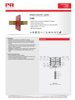
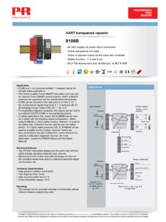
1 Universal transmitter4114 Input for RTD, TC, Ohm, potentiometer, mA and V 2-wire supply > 16 V FM-approved for installation in Div. 2 Output for current and voltage Universal AC or DC supply ApplicationsAdvanced featuresProgrammable by way of detachable display front (4501),process calibration, signal simulation, password protection,error diagnostics and help text available in several languages. ApplicationLinearized, electronic temperature measurement with RTD orTC sensor. Conversion of linear resistance variation to a standard analogcurrent / voltage signal, from solenoids and butterflyvalves or linear movements with attached potentiometer. Power supply and signal isolator for 2-wire transmitters.
2 Process control with standard analog output. Galvanic separation of analog signals and measurement offloating signals. The 4114 is designed according to strict safety requirementsand is therefore suitable for application in SIL 2 installations. Technical characteristicsWhen 4114 is used with the 4501 display / programming front,all operational parameters can be modified to suit anyapplication. As the 4114 is designed with electronic hardwareswitches, it is not necessary to open the device for setting ofDIP-switches. A green / red front LED indicates normal operation andmalfunction. Continuous check of vital stored data for safety reasons. 3-port kVAC galvanic isolation. This page is automatically generated on the basis of information provided on and affiliated websites.
3 It is provided to you as a service and for informationpurpose only. While we have attempted to maintain the information as accurately as possible, the page may contain errors or omissions for which we disclaim any and all liability4114-120617 Environmental ConditionsOperating C to +60 CStorage C to +85 CCalibration CRelative < 95% RH (non-cond.)Protection specificationsDimensions (HxWxD)..109 x x 104 mmDimensions (HxWxD) w/ 4501/ x x 116 / 131 mmWeight gWeight incl. 4501 / 4511 (approx.)..160 g / 245 gWire x mm2 stranded wireScrew terminal 1 gCommon specificationsSupplySupply voltage, VAC, Hz mA SB / 250 VACMax. required WIsolation voltageIsolation voltage, test kVAC / 250 VACR esponse timeTemperature input ( , ).
4 1 smA / V input ( , ).. 400 msAuxiliary supplies2-w. supply (term. ).. VDC / enabler 4511/ Programming front 4501 Signal / noise 60 dB ( kHz) than of sel. rangeEMC immunity < of spanExtended EMC immunity: NAMURNE21, A criterion, < 1% of spanInput specificationsRTD inputRTD ;Pt300/400/500/1000;Ni50/100/120/1000;Cu 10/20/50/100 Cable resistance per (max.)Sensor mAEffect of sensor cable resistance(3-/4-wire)..< / Sensor error circuit < 15 Linear resistance inputLinear resistance ..10000 Potentiometer inputPotentiometer ..100 k TC inputThermocouple , E, J, K, L, N, R, S, T, U,W3, W5, LRCold junction compensation(CJC) via ext. sensor inconnector C 1 C, C C 2 CCJC via int.
5 Mounted ( C + C * t) t =..Internal error error current: Whendetecting / 2 A / 0 ACurrent inputMeasurement mAProgrammable measurement and mAInput 20 + PTC 50 Sensor error detection: Loopbreak inputMeasurement VDCP rogrammable measurement , 0 , 0 VDCI nput 10 M Output specificationsCurrent outputSignal mAProgrammable signal / / / (@ current output).. 800 Load of span / 100 Sensor error / / 23 mA / noneNAMUR NE43 mA / mAOutput limitation, on mA mAOutput limitation, on mA mACurrent 28 mAVoltage outputSignal VDCP rogrammable signal ; 0 ; 0 ; ; ; VLoad (@ voltage output).. 500 k of of the currently selectedmeasurement rangeObserved authority 020 508 / no.
6 14 DNV-GL f. Certific. No. RO Mutual Recognition assessed for use inSIL applications