Transcription of 4114 - PR electronics
1 4114 Universal transmitter No. 4114V104-UKFrom ser. no. 1215240011533PR electronics A/S tilbyder et bredt program af analoge og digitale signalbehandlingsmoduler til industriel automation. Programmet best r af Isolatorer, Displays, Ex-barrierer, Temperaturtransmittere, Universaltransmittere mfl. Vi har modulerne, du kan stole p i selv barske milj er med elektrisk st j, vibrationer og temperaturudsving, og alle produkter opfylder de strengeste internationale standarder. Vores motto Signals the Best er indbegrebet af denne filosofi og din garanti for electronics A/S offers a wide range of analog and digital signal conditioning devices for industrial automation.
2 The product range includes Isolators, Displays, Ex Interfaces, Temperature Transmitters, and Universal Devices. You can trust our products in the most extreme environments with electrical noise, vibrations and temperature fluctuations, and all products comply with the most exacting international standards. Signals the Best is the epitome of our philosophy and your guarantee for electronics A/S offre une large gamme de produits pour le traite ment des signaux analogiques et num riques dans tous les domaines industriels. La gamme de produits s tend des transmetteurs de temp rature aux afficheurs, des isolateurs aux interfaces SI, jusqu aux modules universels.
3 Vous pouvez compter sur nos produits m me dans les conditions d utilisation s v res, bruit lectrique, vibrations et fluctuations de temp rature. Tous nos produits sont conformes aux normes internationales les plus strictes. Notre devise SIGNALS the BEST c est notre ligne de conduite - et pour vous l assurance de la meilleure qualit .PR electronics A/S verf gt ber ein breites Produktprogramm an analogen und digitalen Signalverarbeitungsger te f r die in-dustrielle Automatisierung. Dieses Programm umfasst Displays, Temperaturtransmitter, Ex- und galvanische Signaltrenner, und Universalger te. Sie k nnen unsere Ger te auch unter extremen Einsatzbedingungen wie elektrisches Rauschen, Ersch tterungen und Temperaturschwingungen vertrauen, und alle Produkte von PR electronics werden in berein stimmung mit den strengsten internationalen Normen produziert.
4 Signals the Best ist Ihre Garantie f r Qualit t!DKUKFRDE4114V104-UK 1 UNIVERSAL TRANSMITTER 4114 CONTENTSW arning .. 2 Symbol identification .. 3 Safety instructions .. 3 How to demount system 4000 .. 5 When front LED lights red / display shows .. 5 Advanced features .. 6 Application .. 6 Technical characteristics .. 6PR 4501 display / programming front .. 7 Mounting / demounting the PR 4501/4511 .. 9 Order codes .. 10 Electrical 10 Display readout on the 4501 of sensor error detection and input signal outside range .. 13 Sensor error detection limits .. 14 Error indications .. 14 Connections.
5 15 Block diagram .. 16 Configuration / operating the function keys .. 17 Routing diagram .. 20 Routing diagram, Advanced settings ( ) .. 22 Scrolling help text in display line 3 .. 232 4114V104-UKWARNINGThis device is designed for connection to hazardous electric voltages. Ignoring this warning can result in severe personal injury or mechanical damage. To avoid the risk of electric shock and fire, the safety instructions of this manual must be observed and the guidelines fol lowed. The specifications must not be exceeded, and the device must only be applied as described in the following. Prior to the commissioning of the device, this manual must be examined carefully.
6 Only qualified personnel (technicians) should install this device. If the equipment is used in a manner not specified by the manufacturer, the protection provided by the equipment may be SYSTEM 4000 must be mounted on a DIN rail according to DIN the device is fixed, do not connect hazardous voltages to the device. The following operations should only be carried out on a discon-nected device and under ESD safe conditions: General mounting, connection and disconnection of wires. Troubleshooting the of the device and replacement of circuit breakers must be done by PR electronics A/S OUS VOLTAGEINSTAL-LATIONGENERALWARNINGDo not open the front plate of the module as this will cause damage to the connector for the display / programming front PR 4501.
7 This module contains no DIP-switches or 3 SYMBOL IDENTIFICATIONT riangle with an exclamation mark: Warning / demand. Potentially lethal situations. The CE mark proves the compliance of the device with the essential requirements of the directives. The double insulation symbol shows that the device is protected by double or reinforced insulation. SAFETY INSTRUCTIONSDEFINITIONSH azardous voltages have been defined as the ranges: 75 to 1500 Volt DC, and 50 to 1000 Volt AC. Technicians are qualified persons educated or trained to mount, operate, and also troubleshoot technically correct and in accordance with safety regulations. Operators, being familiar with the contents of this manual, adjust and operate the knobs or potentiometers during normal operation.
8 RECEIPT AND UNPACKINGU npack the module without damaging it. The packing should always follow the module until this has been permanently mounted. Check at the receipt of the module whether the type corresponds to the one direct sunlight, dust, high temperatures, mechanical vibrations and shock, as well as rain and heavy moisture. If necessary, heating in excess of the stated limits for ambient temperatures should be avoided by way of ventilation. All devices fall under Installation Category II, Pollution Degree 1, and Insulation Class technicians who are familiar with the technical terms, warnings, and instruc-tions in the manual and who are able to follow these should connect the there be any doubt as to the correct handling of the device, please contact your local distributor or, alternatively,PR electronics A/S 4114V104-UKMounting and connection of the device should comply with national legislation for mounting of electric materials, wire cross section, protective fuse, and location.
9 Descriptions of input / output and supply connections are shown in the block diagram and side following apply to fixed hazardous voltages-connected devices:The max. size of the protective fuse is 10 A and, together with a power switch, it should be easily accessible and close to the device. The power switch should be marked with a label indicating that it will switch off the volt age to the of manufacture can be taken from the first two digits in the serial INSTALLATION REQUIREMENTSUse 60/75 C copper conducters only For use only in pollution degree 2 or better Max. ambient temperature .. 60 C Max. wire size .. AWG 26-14 UL file number .. E231911 CALIBRATION AND ADJUSTMENTD uring calibration and adjustment, the measuring and connection of external voltages must be carried out according to the specifications of this manual.
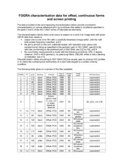
10 The technician must use tools and instruments that are safe to OPERATIONO perators are only allowed to adjust and operate devices that are safely fixed in panels, etc., thus avoiding the danger of personal injury and damage. This means there is no electrical shock hazard, and the device is easily disconnected, the device may be cleaned with a cloth moistened with distilled the extent that the instructions in this manual are not strictly observed, the custom er cannot advance a demand against PR electronics A/S that would otherwise exist according to the concluded sales 5 HOW TO DEMOUNT SYSTEM 4000 First, remember to demount the connectors with hazardous 1: Detach the device from the DIN rail by lifting the bottom lock.