Transcription of Flame Photometer - Jenway
1 Flame PhotometerModels PFP7 and PFP7/COperating and Service Manual500 7951 PFP7/REV C/01-08 SafetyPlease read this information carefully prior to installing or using this The unit described in this manual is designed to be operated only by trained adjustments, maintenance and repair must be carried out as defined in this manualby a person qualified to be aware of the hazards It is essential that both operating and service personnel employ a safe system of workin addition to the detailed instructions provided in the The covers of the unit should only be removed by personnel who have been trained toavoid the risk of shock. At this point the unit must be disconnected from all services and References should always be made to the health and safety data supplied with anychemicals used. Generally accepted laboratory procedures for safe handling ofchemicals should be If it is suspected that safety protection has been impaired in any way, the unit must bemade inoperative and secured against any intended operation.
2 The fault conditionshould be reported immediately to the appropriate servicing authority. In all such reportsthe serial number of the Flame Photometer must be Please read the operating precautions in section For further help and advice please contact your localdistributor, for service enquiries please A/12-082 PFP7/REV C/01-08 Contents:SECTION 1 .. Instrument Principles of operation .. 2 .. Services 3 .. 11 Analysis Calibration Sample Dilution ..13 SECTION 4 .. Front and rear panel Operation .. Calibration: Calibration: PFP7/C .. Operating Good practice guidelines ..20 SECTION 5 .. 21 Accessories .. Water separator .. Compressor .. Datalogger .. General .. Weekly Monthly Six-monthly A/12-083 PFP7/REV C/01-08 SECTION 7 .. 25 Trouble shooting .. General .. Unstable results .. Unable to set standard Non-linear Flame will not light.
3 No electrical power .. No reading on Unable to set blank ..27 SECTION 8 .. 28 Service Sample system Combustion and ignition system description .. Optical system Power supply Signal processing description ..33 Component replacement .. Chimney and optical Power supply Main PCB Fuel solenoid Fuel needle Spark generator replacement .. Air regulator assembly replacement ..43 SECTION 10 .. 44 Spare Minor spares kit (500 172) .. Major spares kit (500 173) ..44 PFP7 MkII/Rev A/12-084 PFP7/REV C/01-08 Section Instrument descriptionThe PFP7 and PFP7/C are low temperature, single channel emission Flame photometersdesigned for the routine determination of sodium (Na) and potassium (K). Additional filters areavailable for the determination of lithium (Li), calcium (Ca) and barium (Ba). Both versions arefitted with automatic Flame failure detection for user safety, making them ideal for use in clinical,industrial or educational applications.
4 The model PFP7/C is specifically designed for use inclinical applications. The in-built lineariser circuitry enables readings of both Na and K, at normalclinical serum concentrations to be displayed directly in mmol/l. Serum samples must be diluted200:1 or 100:1 prior to presentation to the Flame Photometer . Jenway are able to offer a diluterto enable this to be carried out efficiently and Principles of operationFlame photometry relies upon the fact that the compounds of the alkali and alkaline earthmetals can be thermally dissociated in a Flame and that some of the atoms produced will befurther excited to a higher energy level. When these atoms return to the ground state they emitradiation which lies mainly in the visible region of the spectrum. Each element will emit radiationat a wavelength specific for that element. The table below gives details of the measurableatomic Flame emissions of the alkali and alkaline earth metals in terms of the emissionwavelength and the colour Wavelength (nm) Flame ColourSodium (Na)589 YellowPotassium (K)766 VioletBarium (Ba)554 Lime GreenCalcium (Ca)622*OrangeLithium (Li)670 Red*Note: Calcium is measured by using the calcium hydroxide band emission at 622nm as theCalcium main atomic emission occurs at certain ranges of concentration the intensity of the emission is directly proportional to thenumber of atoms returning to the ground state.
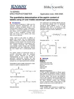
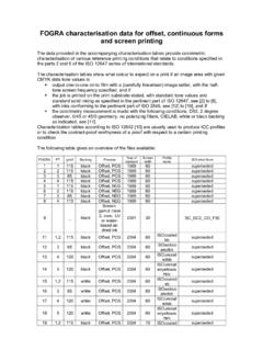
5 This is in turn proportional to the absolutequantity of the species volatized in the Flame , light emitted is proportional to can be seen that if the light emitted by the element at the characteristic wavelength is isolatedby an optical filter and the intensity of that light measured by a photo-detector, then an electricalsignal can be obtained proportional to sample concentration. Such an electrical signal can beprocessed and the readout obtained in an analogue or digital simple Flame Photometer consists of the following basic components:a) The burner: a Flame that can be maintained in a constant form and at a ) Nebuliser and mixing chamber: a means of transporting a homogeneous solution intothe Flame at a steady ) Simple colour filters (interference type): a means of isolating light of the wavelength tobe measured from that of extraneous ) Photo-detector: a means of measuring the intensity of radiation emitted by the A/12-085 PFP7/REV C/01-08 Figure : Schematic diagram showing the component parts of a Flame analysis of alkali and alkaline earth metals by Flame photometry has two major advantages:i.
6 Their atoms reach the excited state at a temperature lower than that at which mostother elements are Their characteristic wavelengths are easily isolated from those of most other elementsdue to wide spectral analysis of Na, K, Li, Ba and Ca are typically determined at low temperatures, 1500-2000 C, therefore suitable fuel mixtures are propane/air, butane/air and natural chamberFilterFlamePhotodetectorGas inletDrain U tubeWasteReadoutAmplifierLensAir inletBurnerNebuliserMixing chamberFilterFlamePhotodetectorGas inletDrain U tubeWasteReadoutAmplifierLensAir inletPFP7 MkII/Rev A/12-086 PFP7/REV SpecificationPFP7 PFP7/CRanges:-120-160 mmol/l Na (linearised) mmol/l KLimits of :1% Coefficient of variation ( ) for 20 consecutive samplesusing 10ppm Na set to read taken at 20 second : thesamplestandarddeviationX100mean readingAnd sample standard deviation as:Where x is the reading, x is the mean readings of the series and n isthe number of :Better than 2% when concentration of 3ppm Na and K and 5ppm Liare set to read :Interference from Na, K and Li when equal in concentration to thetest element will be less than :Better than 2% over 5 minutes when continuously aspirating 10ppm,sample set to read drift better than 2% per Note warm up :Between 2 and 6 Output:Nominal volt for readout of Up:The Flame must be alight for at least 15 minutes to ensureachievement of the above stated :Electrical:90-125V or 190-250V @ 50 :Moisture and litres/minute at 1kg/cm2(14psi).
7 Fuel:Propane, butane, natural gas or :15 C to 35 CSize:420x360x300mmWeight:8kg(x-x2)n-1(x -x2)n-1(x-x2)n-1 PFP7 MkII/Rev A/12-087 PFP7/REV C/01-08 Section Services requiredThe fuel and air supplies to the instrument must be clean and dry and supply pressuresregulated within the limits specified. Any contamination, moisture or variation in supply pressurewill directly affect the performance of the : The instrument will only operate with the correct type of air compressor and Voltage90 - 125V or 190 - 250V @ 50 or Fuel Propane or butane regulated to 10-15 inches water gauge ( or ). Natural gas at mains pressure between 3 and 10 inches water gauge ( ). as for propane. Suitable regulators are available from Jenway ; refer to Section AirA supply of dry, clean and pulse-free air at a pressure between 14 and 30 psi (approx. 1-2kg/cm2) at 6 litres/minute is required. A suitable compressor and water separator are availablefrom Jenway ; refer to Section DrainThe instrument will need to be sited near a drain or sink to enable disposal of waste liquid.
8 Asuitable receptacle can be utilised if provision is made for easy disposal of its :The waste liquid will still contain any hazardous materials that were in the originalsamples and should be handled and disposed of with the same care. Waste liquid shouldalways be considered to be of a pathogenic nature where the instrument is used in a UnpackingRemove the instrument from the packaging and ensure the following items are present:Part CodeModel PFP7 or PFP7/C Flame photometerAuxiliary power plug009 035 Mains cable with connector (plug optional as ordered)013 046 Nebuliser inlet tube (500mm)500 193 Gas tube, low pressure (2 metres)500 191 Silicon rubber tube (drain)023 003 Air tube (2 metres)500 192 Nozzle 1: gas026 012 Nozzle 2: air026 013 Allen key, 037 Adjustable hose clip060 083 Drain trap500 018 Drain trap clip500 114 Nebuliser cleaning wire500 194 Any shortages or damage should be reported immediately to the manufacturer or A/12-088 PFP7/REV AssemblyPlace the instrument on a bench and proceed as follows (seeFigures ).
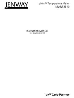
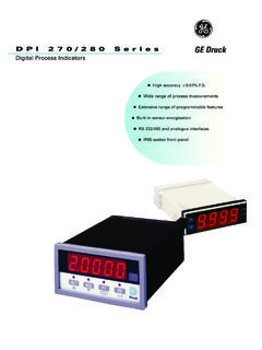
9 1. Take the mixing chamber assembly and ensure that the fluted burner (1) is in place(remove the retaining tape); offer up to the chimney. Look down the chimney andensure that the burner locates centrally in the inner chimney. Screw the locking ring (2)onto the threaded boss provided and tighten until finger tight, ensuring that the mixingchamber is at right angles to the side of the Fit the nebuliser (3) into the end cap and screw on the tube (4) provided. Ensure thatthe sealing olive is fitted correctly between the nebuliser and the screw on If natural gas is to be used, remove the restrictor (5) fitted into the end of the fuel inlet(6) on the mixing chamber. The restrictor should remain in place if butane, propane is to be used as fuel. Keep the restrictor screw in case of any future change ingas supply. Push the fuel tubing onto the fuel inlet connector (7). This tube does notneed : Assembly of the mixing chamber, burner and Take the drain trap clip (8) and, with the screw provided, fix to the hole situated at thechimney end of the rear panel.
10 Fix a length of silicon rubber tubing (9) onto the side porton the drain trap such that it is long enough to reach either the sink or the wastereceptacle to be used. Fit the drain trap into the clip on the rear panel and run the shortpiece of tubing (10) from the bottom of the drain trap to the drain trap outlet (11) on thebottom of the mixing chamber. This tube can be pushed on and does not A/12-089 PFP7/REV C/01-08 Figure : Rear panel showing the drain trap, air and fuel InstallationWARNINGThe exhaust gases from the chimney are very hot. Noobstruction should be placed above the instrument and theinstrument should be located in a position that makesaccidental contact with the chimney or its exhaust instrument needs to be operated in a well-ventilated room(although very strong draughts should be avoided).Ensure the air tubing is routed away from sources of the air and fuel inlet connectors to the ports provided on the rear of the Fit the appropriate lengths of tubing to the connectors (12 and 13) and secure with thescrew clips provided.