Transcription of 433 MHz RF Receiver STR-433 1. Overview
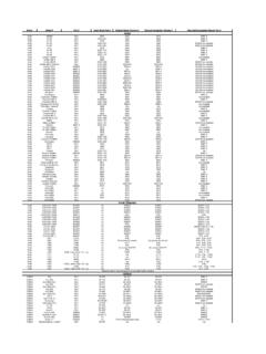
1 Sunrom Technologies Visit us at 1 433 mhz RF Receiver STR-433 1. Overview The STR-433 is ideal for short-range remote control applications where cost is a primary concern. The Receiver module requires no external RF components except for the antenna. It generates virtually no emissions, making FCC and ETSI approvals easy. The super-regenerative design exhibits exceptional sensitivity at a very low cost. The manufacturing-friendly SIP style package and low-cost make the STR-433 suitable for high volume applications. 2. Features Low Cost 5V operation current drain No External Parts are required Receiver Frequency: MHZ Typical sensitivity: -105dBm IF Frequency: 1 MHz 3. Applications Car security system Sensor reporting Automation system Remote Keyless Entry (RKE) Remote Lighting Controls On-Site Paging Asset Tracking Wireless Alarm and Security Systems Long Range RFID Automated Resource Management 4.
2 Specification Parameter Symbol Min Typ. Max Unit Operating Voltage Vcc VDC Operating Current Icc - mA Reception Bandwidth BW rx - - MHz Center Frequency Fc - - MHz Sensitivity - - -105 - dBm Max Data Rate - 300 1k 3K Kbit/s Turn On Time - - 25 - ms Operating Temperature T op -10 - +60 C Sunrom Technologies Visit us at 2 5. Pin Outs Pin Name Description ANT Antenna input. GND Receiver Ground. Connect to ground plane. VCC(5V) VCC pins are electrically connected and provide operating voltage for the Receiver . VCC can be applied to either or both. VCC should be bypassed with a .1 F ceramic capacitor. Noise on the power supply will degrade Receiver sensitivity. DATA Digital data output. This output is capable of driving one TTL or CMOS load. It is a CMOS compatible output. 6. Mechanical Drawing Mechanical Drawing (Dimensions in Inches) Sunrom Technologies Visit us at 3 7.
3 Operation Super-Regenerative AM Detection The STR-433 uses a super-regenerative AM detector to demodulate the incoming AM carrier. A super-regenerative detector is a gain stage with positive feedback greater than unity so that it oscillates. An RC-time constant is included in the gain stage so that when the gain stage oscillates, the gain will be lowered over time proportional to the RC time constant until the oscillation eventually dies. When the oscillation dies, the current draw of the gain stage decreases, charging the RC circuit, increasing the gain, and ultimately the oscillation starts again. In this way, the oscillation of the gain stage is turned on and off at a rate set by the RC time constant. This rate is chosen to be super-audible but much lower than the main oscillation rate. Detection is accomplished by measuring the emitter current of the gain stage. Any RF input signal at the frequency of the main oscillation will aid the main oscillation in restarting.
4 If the amplitude of the RF input increases, the main oscillation will stay on for a longer period of time, and the emitter current will be higher. Therefore, we can detect the original base-band signal by simply low-pass filtering the emitter current. The average emitter current is not very linear as a function of the RF input level. It exhibits a 1/ln response because of the exponentially rising nature of oscillator start-up. The steep slope of a logarithm near zero results in high sensitivity to small input signals. Data Slicer The data slicer converts the base-band analog signal from the super-regenerative detector to a CMOS/TTL compatible output. Because the data slicer is AC coupled to the audio output, there is a minimum data rate. AC coupling also limits the minimum and maximum pulse width. Typically, data is encoded on the transmit side using pulse-width modulation (PWM) or non-return-to-zero (NRZ). The most common source for NRZ data is from a UART embedded in a micro-controller.
5 Applications that use NRZ data encoding typically involve microcontrollers. The most common source for PWM data is from a remote control IC such as the HC-12E from Holtek or ST14 CODEC from Sunrom Technologies. Data is sent as a constant rate square-wave. The duty cycle of that square wave will generally be either 33% (a zero) or 66% (a one). The data slicer on the STR-433 is optimized for use with PWM encoded data, though it will work with NRZ data if certain encoding rules are followed. Power Supply The STR-433 is designed to operate from a 5V power supply. It is crucial that this power supply be very quiet. The power supply should be bypassed using a low-ESR ceramic capacitor and a tantalum capacitor. These capacitors should be placed as close to the power pins as possible. The STR-433 is designed for continuous duty operation. From the time power is applied, it can take up to 750mSec for the data output to become valid. Antenna Input It will support most antenna types, including printed antennas integrated directly onto the PCB and simple single core wire of about 17cm.
6 The performance of the different antennas varies. Any time a trace is longer than 1/8th the wavelength of the frequency it is carrying, it should be a 50 ohm microstrip. Sunrom Technologies Visit us at 4 8. Typical Application Remark: Antenna length about: 17cm for 433 mhz 9. Ordering Information Model Description STR-433 433 mhz RF Receiver