Transcription of 440 & 450 Electronic Vibration Switches Installation Manual
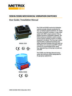
1 440 & 450 Electronic Vibration SWITCHESI nstallation Manual1. Introduction The single setpoint models (SR) contain one trip limit for shutdown. The optional dual setpoint models (DR) contain two indepen-dent trip limits; one for alarm and one for shutdown. Shutdown and alarm limits are in engineering units of velocity. In addition, a 4-20 mA output proportional to Vibration velocity is 440 and 450 use identical design and differ only in the enclosure. The model 440 is designed to be used in non-hazardous or non-incendive hazardous location (Class I, Division 2, Groups B, C, D, and NEMA 4X). The model 450 is designed to meet explosion-proof requirements for Class I, Division 1, Groups B, C, D installations. Unless otherwise noted, all discussions and diagrams herein assume the model 440, but apply equally to the model Key Capabilities Shutdown and alarm settings are based on Vibration severity. The internal sen-sor (unless the external sensor option has been specified (Ordering Option I=5 see note in Section ) is a piezo-electric crystal with built in microelec-tronics to reduce noise sensitivity.)
2 The output signal is electronically integrat-ed to measure and trip on velocity. Calibrated setpoint controls permit set-point adjustment of Vibration velocity levels up to full scale range. DR model Doc# 90018-031 REV M (July 2017) Doc# 90018-031 REV M (July 2017) Page 2 of 16 NOTE: Discrete outputs should be manually bypassed during this procedure, particularly if used to trip the machine. They will change state after the time delay, and should be externally jump-ered or otherwise disabled to prevent nuisance trips. Calibrated setpoint controls enable operator to set specific velocity alarm/shutdown time delay of 2-15 illuminates immediately when Vibration ex-ceeds setpoint (but alarm or shutdown discrete outputs will change state only after time delay). User InterfaceKey Capabilities (continued) Switches have dual setpoints one for alarm and one for shutdown that are indepen-dently adjustable. 4-20 mA output provides a convenient interface for trending and displaying Vibration amplitude in a programmable logic controller (PLC), SCADA system, data logger, or oth-er instrumentation.
3 4mA corresponds to no Vibration , and allows the user to distinguish between no power to the switch (0mA) and a functional switch but with no Vibration present (4mA). 20mA corresponds to full scale Vibration amplitude. Discrete outputs used for alarming and shutdown can be selected from triac, solid-state analog switch (FET), or electromechanical relays, but must be specified at time of ordering. These outputs are independently configurable for open on alarm/shutdown or close on alarm/shutdown . An adjustable (2-15 seconds) time delay is standard. This prevents false alarms/shut-downs on high startup vibrations and also from non repetitive transient events. Self-test and verification: An LED adjacent to each setpoint control illuminates the instant the measured Vibration level exceeds the setpoint. The unit can be periodically verified on line by turning the setpoint control down until the LED comes on. This set-ting is then compared with the Vibration amplitude measured via a portable Vibration meter at the same location as the switch s sensing element, providing a verification check of the # 90018-031 REV M (July 2017) Page 3 of 16 NOTE: Turning either adjustment knob to the TEST position reduces the corresponding setpoint to its minimum allowable value, effec-tively meaning that any Vibration will exceed the setpoint.
4 Although the LED will come on immediately, the discrete output will change state only after the duration of the adjustable time delay has elapsed. If the TEST position is maintained for less than the duration of the time delay, the discrete output will not change state. VDE approved terminal strip accepts #12 AWG wire. All hardware is discrete output is inde-pendently field configurable to open on alarm ( ) or close on alarm ( )3. SAFETY WARNINGSCAUTION - SHOCK HAZARD 230/110 VOLTSThe terminal block inside the 440 is connected to AC power (110 VAC or 230 VAC depending on model) except DC input power models. If adjustments to the device are being made with power applied, exer-cise caution to avoid contact with the terminal block screws by any part of the body or electrically conductive OPERATIONM odel 440 and 450 Vibration Switches must be installed and operated as described in this Manual and in accordance with published datasheet specifications.
5 Operation outside these limits may adversely affect the switch s alarming and shutdown capabilities, resulting in damage to machinery and property as well as jeopardizing personnel SPECIFICATIONSR efer to product datasheet 1004730, available online at Doc# 90018-031 REV M (July 2017) Page 4 of 16 4. MECHANICAL Installation Where to Mount the SwitchIt is desirable to mount the Electronic switch (or transducers for Switches with external transducer option) on a bearing housing, since the forces generated by the rotating parts through unbalance, misalignment, bearing wear, etc., are transmitted to the machine s cas-ing through the bearing housings are curved so it is necessary to attach a bracket with a flat surface for mounting the switch. If the machine has bolted end plates on the bearings or horizontally split bearing housings, these bolts can be used to attach the bracket. When bolt holes are not available or are not suitable, an alternative way is to weld an angle iron bracket similar to that in the sketch, but oriented so as to straddle the bearing housing.
6 The best approach will typically be to mount a gusseted bracket, as shown below. The guiding principle is to ensure that the bracket is suitably stiff such that machinery Vibration is completely transmitted through the bracket to the Vibration switch or sensor. Problems can occur when the bracket is too compliant, and may allow bracket resonance to amplify the actual machinery Vibration , resulting in false shutdowns or alarms. For many applications, 3/8 Inch material (preferably steel) will be suitable. Switch Sensitive AxisThe sensitive Vibration measuring axis is perpendicular to the mounting base of the unit ( Vibration switch or transducer). Always mount the unit such that the desired Vibration of the equipment being monitored will occur along this axis. NOTE: Models using an external sensor will be sen-sitive along the sensor s axis, not the switch s axis. Doc# 90018-031 REV M (July 2017) Page 5 of 16 Choosing Mounting OrientationThe Vibration switch can be mounted in the vertical or horizontal orientation (or anything in between) without a change in its sensitivity.
7 Ideally, the mounting orientation will be chosen by measuring the Vibration levels in both directions with a Vibration meter and then select-ing the direction in which the highest Vibration occurs. This will typically be horizontal, since most machine structures are less rigid horizontally than vertically. Number of Points per MachineAnywhere from one to four Switches are used per machine (depending on how critical the machine is to the process or how expensive it is), one on each end of the motor and one on each end of the compressor, fan, pump or whatever is being driven. If there is a gear box in between, one may be used here is quite common to use only one switch. In this case, it is best to mount on or near the driven bearing. For example, if you have a motor and large fan with a bearing on each end of the fan, the fan bearing on the motor side would be the driven bearing. It will usually see the highest forces and have the highest Vibration Mounting at other LocationsWhen it is not possible to mount the switch directly on the bearing housing, the switch can be located elsewhere, keeping in mind that it is usually machinery Vibration that is being measured (not bracket, piping, or other Vibration ).
8 Do not mount the switch in locations where very little machinery Vibration is transmitted, as the switch will be less sensitive to damaging changes in machinery Vibration levels. Again, it is desirable to survey the machine with a Vibration meter. If the level at the intended location is not attenuated by more than about 50% relative to the levels directly on the bearing housing, it will probably be satisfac-tory. However, alarm and shutdown settings should then be reduced proportionately as Mounting SurfaceChoose or fabricate a solid (rigid) surface (on the equipment being monitored) to mount the Vibration switch or transducer. This will ensure transfer of the Vibration to the Vibration transducer, while not introducing erroneous vibrations. In addition, the surface presented to the base of the unit should be flat. Fasten using sturdy hardware at all places provided. Temperature ConsiderationsThe switch is designed to dissipate internal heat by conduction through its base.
9 Hence, it is important to keep the mounting surface below the switch max temperature limit of 140 F. If the equipment being monitored is going to exceed this limit, consideration should be given to either using one of the remote transducers, or thermally isolating the switch. To ensure accurate switch performance, a warm up time of 5 minutes is Elevation ConsiderationsThe reduced atmospheric pressure at elevations more than 2,000 meters (~6600 feet) above Doc# 90018-031 REV M (July 2017) Page 6 of 16 sea level does not allow heat to dissipate as readily as at lower elevations, and the maximum operating temperature must be de-rated by 2% per 300 meters. Thus, a switch installed at an elevation of 2,600 meters will have a maximum operating temperature 4% lower than a switch installed between seal level and 2,000 meters. Refer to datasheet 1004730 for complete specifications. Cable/WiringThe method chosen to electrically connect to the switch or transducer should be mechani-cally flexible, to eliminate the measurement of Vibration of material not of interest (piping, etc.)
10 , and provide a moisture barrier as seal tight and other flexible conduit have been used successfully, in areas of extreme humidity or moisture it is recommended that a SO type cable together with a suitable rain-tight CGB fitting be stress should be possible on the wiring to the terminal block. If such protection is not provided by the conduit system, some form of stress relief must be installed where the wir-ing exits the reduce susceptibility to EMI/RFI, any signal-level wiring such as transducer, reset, lockout, or 4-20 mA loop should utilize shielded cable in EMI-proof conduit, separate from any power wiring. The signal-wiring conduit and power-wiring conduits can be connected at the switch entry via a T SealingIn installations where temperature and humidity conditions vary around the dew point, it is important that the cover be evenly and firmly fastened down with the four screws provided (model 440) or via the threaded cover (model 450).