Transcription of 475 Field Communicator
1 Getting Started475 Field Communicator2 Introduction3 2015 Emerson Process Management. All rights reserved. HART is a registered trademark of the HART Communication is a trademark of the Fieldbus is a registered trademark of the Infrared Data is a registered trademark of the Bluetooth SIG, Emerson logo is a trademark and service mark of Emerson Electric other marks are the property of their respective 475 Field Communicator Getting Started Guide provides basic guidelines, precautions, and setup information for the 475 Field Communicator . It does not provide in-depth instructions for configuration, diagnostics, maintenance, service, troubleshooting, or Intrinsically Safe (IS) installations. Refer to the 475 Field Communicator User s Manual on the Resource CD or DVD or for more instructions. The 475 Field Communicator supports HART and FOUNDATION fieldbus devices, letting you configure or troubleshoot in the Field . Electronic Device Description Language (EDDL) technology enables the 475 Field Communicator to communicate with a variety of devices independent of device manufacturer.
2 WARNINGE xplosions could result in serious injury or death: Use in an explosive environment must be in accordance with the appropriate local, national, and international standards, codes, and practices. Please review the Reference Information and Product Certifications sections of the 475 Field Communicator User s Manual for any restrictions associated with safe use. Electrical shock can result in serious injury or NOTICEThis device complies with Part 15 of the FCC Rules. Operation is subject to the following two conditions: (1) this device may not cause harmful interference, and (2) this device must accept any interference received, including interference that may cause undesired Field Communicator overview4475 Field Communicator OVERVIEWThe portable 475 Field Communicator includes a color LCD touch screen, a Lithium Ion battery (Power Module), a SH3 processor, memory components, System Card, and integral communication and measurement using the 475 Field Communicator to communicate with devices, follow all standards and procedures applicable to the location.
3 Failure to comply may result in equipment damage and/or personal injury. Understand and comply with the sections in this manual. Working in a hazardous areaA 475 Field Communicator that meets the Intrinsic Safety requirements (IS-approved) can be used in Zone 0 (FM), Zone 1, or Zone 2, for Group IIC, and Class I, Division 1 and Division 2, Groups A, B, C, and D IS-approved 475 Field Communicator may be connected to loops or segments that are attached to equipment located in Zone 0, Zone 1, Zone 2, for Group IIC; Zone 20, Zone 21, Zone 22, and Class I, Division 1 and Division 2, Groups A, B, C, and D 475 Field Communicators have an additional label on the back of the Communicator that lists the can install or remove the Li-Ion battery in a hazardous area environment. You cannot charge the battery in this environment because the power supply/charger (00375-0003-0005) is not the touch screen and keypadThe touch screen and keypad let you select menu items and enter text.
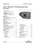
4 Use the provided stylus or the up and down arrow keys on the keypad to select a menu item. See Figure 1 for the location of the stylus. Double-tap the selected item on the screen, tap an icon, or press the right arrow key on the keypad to open a menu item. CAUTIONC ontact the touch screen using blunt items only, preferably the stylus included with the 475 Field Communicator . Sharp instruments, such as screwdrivers, can damage the touch screen and void the warranty. Repairing the touch screen requires replacement of the entire display assembly, which is possible only at an authorized service Field Communicator overview5 Figure 1. 475 Field Communicator with the Protective Rubber BootHART and FOUNDATION fieldbus communication terminals (top)Stylus (in thestrap)Bluetooth light IrDA interface (top) Touch screendisplayStrap attachment (top)Backlight keyStrap attachment (side)Enter keyFunction key and light(for multiple-key combination functionality)Li-Ion battery(back) andSystem Card(internal)Strap attachment (side)Strap attachment (side)Lightsilluminated bypressing theCharge Indicatorbutton (side)Alphanumeric keypadTab keyNavigation keys(four arrow keys)Strap attachment(side)Power key andlightChargeIndicatorbutton (side)Green power supply/charger connector on the battery (side)475 Field Communicator overview6 Battery and power supply/chargerUnderstand and follow the precautions below before using your battery or power supply/charger.
5 See power supply/charger manual for more information. Protect the battery and power supply/charger from moisture, and respect operating and storage temperature limits. See the 475 Field Communicator User s Manual for temperature limits. The power supply/charger is for indoor use only. Do not cover the battery or power supply/charger, subject it to prolonged periods of direct sunlight, or place it upon or next to heat-sensitive materials. Charge the battery with only the power supply/charger. The power supply/charger should not be used with other products. Failure to comply may permanently damage your 475 Field Communicator and void the IS approval and the warranty. Do not open or modify the battery or power supply/charger. There are no user-serviceable components or safety elements inside. Opening or modifying them will void the warranty and could cause personal harm. Follow all applicable regulations when transporting a Li-Ion battery.
6 Clean the power supply/charger by clearing the terminal of dirt and debris. However, no cleaning is required. If the power supply/charger is used in a manner not specified by Emerson Process Management, the protection provided by the equipment may be impaired. Charging the batteryPrior to first portable use, fully charge the Li-Ion battery. The power supply/charger has a green connector to match the connector on the battery. The battery can be charged separately or while attached to the 475 Field Communicator . A full charge takes approximately two to three hours, and the 475 is fully operable when charging. An overcharge condition will not occur if the power supply/charger remains connected after charging completes. To maintain performance, charge the battery frequently, preferably after each use. Limit full discharges, if possible. Additional information about maintaining the battery is in the 475 Field Communicator User s supply/charger lightsThree colored lights are on the power supply/charger to indicate the conditions below.
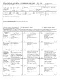
7 Each light displays a different ConditionGreenThe battery is fully green The battery is nearly fully battery is yellowThe power supply/charger is not connected to the 475 Field yellow and redThe remaining charge in the battery is cannot occur. Contact Technical Support for more the System Card and battery7 Figure 2. Back of the 475 Field CommunicatorINSTALLING THE SYSTEM CARD AND BATTERYIf you received a 475 Field Communicator with the System Card already installed, proceed to the "Starting the 475 Field Communicator " Remove the protective rubber boot, if Place the 475 Field Communicator face down on a level, secure With the battery removed, slide the Secure Digital System Card (labeled System Card), with the card contacts facing up, into the System Card socket until it clicks. The System Card socket is spring-loaded. See Figure 2 for the System Card socket location. The System Card is not locked into the System Card socket in Figure 2.
8 CAUTIONThe System Card must be supplied by the 475 Field Communicator manufacturer. Failure to comply will void the IS With the 475 Field Communicator still face down, ensure the two battery retaining screws are loose. 5. Align the battery with the sides of the 475 Field Communicator , and carefully slide the battery forward until it is secure. CAUTIONThe connector pins may be damaged if the battery and 475 Field Communicator are improperly Carefully hand tighten the two battery retaining screws. (Do not over tighten, maximum torque load.) The tops of the screws should be nearly flush with the 475 Field Communicator . Battery retaining screwsLi-Ion batteryConnector pinsSystem Card partially inserted in the System Card socketMain unit labelStrap attachmentStrap attachment IS label (KL option)Stand Bluetooth approval labelRemoving the battery and System Card8 REMOVING THE BATTERY AND SYSTEM CARD 1. Remove the protective rubber boot, if With the 475 Field Communicator off, place it face down on a level, secure Loosen the two battery retaining screws until the top of each screw is above the top of the 475 Field Slide the battery off the 475 Field Communicator .
9 CAUTIONThe connector pins may be damaged if you pull the battery up rather than slide it off the 475 Field Push the System Card into the System Card socket until it clicks and Slide the System Card out of the System Card THE 475 Field COMMUNICATORB efore startup, ensure the 475 Field Communicator is not damaged, the battery is fully seated, all screws are sufficiently tightened, and the communication terminals are free of dirt and start the 475 Field Communicator :1. Press and hold the Power key on the keypad until the green light on that key blinks (approximately two seconds). During startup, the 475 Field Communicator notifies you if an upgrade on the System Card needs to be installed. The Field Communicator Main Menu Use the touch screen or up and down arrow keys to select an icon or menu item. 3. To shut down, press the Power key and tap Shut down from the Power Switch screen. Tap WITH PC APPLICATIONSThe IrDA interface, Bluetooth interface (if licensed), and a supported card reader let the 475 Field Communicator or its System Card communicate with a PC.
10 See Figure 1 for the location of the IrDA interface and the System Card. A card reader can only be used with the Easy Upgrade Utility. See the 475 Field Communicator User s Manual for more information. Connecting to a device9 CONNECTING TO A DEVICEUse the provided lead set to connect the 475 Field Communicator to the loop, segment, or device. Three communication terminals for the lead set are on the top of the 475 Field Communicator . Each red terminal is a positive connection for its protocol, and the black terminal is a common terminal shared by both protocols. An access door ensures that only one pair of terminals is exposed at any one time. Several markings indicate which pair of terminals is for which connections to a HART loop and FOUNDATION fieldbus segment are allowed. The appropriate device description is also required. Refer to the latest version of the 475 Field Communicator User s Manual for 475 Field Communicator draws approximately 12 mA from the fieldbus segment.