Transcription of ˘ 596 E - Spinner II® Products
1 Model 596 HEInstallation InstructionsParts ListService InstructionsBulletin73981 Three connections are required at the centrifuge:1. Oil Inlet (1/2-in. NPT Female Pipe) Unscrew plastic shipping #8 hose from point of highest Oil Outlet (1/2-in. NPT Female Pipe) Unscrew plasticshipping plug. Run #8 hose to crankcase above oil Air Inlet (1 Female Pipe) Unscrew plastic shipping plug. Run #4 hose from any convenient pointon air supply to air valve cartridge inlet. Do not removecartridge loss of cartridge seal may damage Route hoses to clear exhaust and all movingparts and fasten securely. Be certain the pressurized oil supply is to OIL IN port on side of centrifuge and return tocrankcase is from OIL OUT port on bottom.
2 Do not removefull-flow filters. Use the SpinnerII centrifuge only as abypass oil cleaner. Remove any previously installedbypass filters prior to installation of the Spinner II, andblock ports where InstructionsDirty Oil Supply to Centrifuge Oil InletPressure Tap on Engine Most engines, including the latest models from Cummins, Caterpillar, DDC and Mack,provide a 3/8-in. or 1 to supply an auxiliary using end-of-gallery supply points such as the pressure gauge Oil Outlet Return to CrankcaseReturn Opening in Crankcase Most engines have a 1 larger oil return opening provided in thecrankcase wall. If unrestricted, this is an ideal oil outlet line connection Return Problems If there are no availabledrain openings, it may be necessary to drill and tap aninspection plate.
3 Remove the plate before modificationand avoid directing the return flow directly onto movingparts. Request assistance from Spinner II Products . Air SupplyAir for the control mechanism can be taken from any convenient place on the vehicle air system where there is a constant supply of air, preferably from the dry nylon tubing is sufficient or #4 hose can be used if preferred. Air pressure can vary from 35 to125 psig. If over 125 psi, a regulator must be used. The Spinner IIcontrol automatically shuts off the air supply when theengine stops. Air consumption of SCFM is almost too small to II/596 HENet Weight 10 lb ( kg)Mounting LocationInstall at no more than 15 from vertical (temporaryincreases in tilt angle from vehicle operation are not significant).
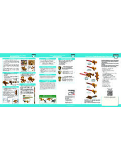
4 The frame rail is the preferred location formounting the centrifuge. Check with manu facturer beforedrilling. Bulletin 71294 contains a drilling the centrifuge directly to the engine is not recommended. The Spinner II centrifuge is a high-speeddevice and is provided with rubber isolators for operatorcomfort, which must be installed as shown above. Careshould be used to prevent metal-to-metal contact with the frame or body, which might result in unnecessarynoise or vibration. The cover clamp can be rotated to any convenient position and tightened by hand 596HE Installation InstructionsDetailed Information AvailableFor optimum performance of your centrifuge, specificinstallation drawings for almost any diesel engine canbe requested from Spinner II 20 30 40 50 60 70 80 90 100 110 120 Inlet Pressure (PSI)10000900080007000600050004000300020 001000 Rotor Speed (rpm) Rate (GPM)Rotor SpeedOil FlowSAE 40 Oil @ 212 FRubber isolator installation3/8-in.
5 (10 mm) Grade 5bolts and nuts tightento 23 lb-ft (31. 2 N-m)Not suppliedModel 596HE Parts ListItem DescriptionPart numberOnly items shown with part numbers are denotes assemblyCentrifuge, Spinner II/Model 596HE , Spinner II/Model 596HE, without kit (1 each items c and d)..73950aCover assembly ..73968bBand clamp ..71266cO-ring (Viton) .. of Service Kit 73950eM10 x 35 bolts ..73970fBody assembly ..73960gCut-out valve kit ..73971hSeal-idle cutout valve ..73980iLower bearing kit ..73972jO-ring (Viton) ..73973kRepair kit-control float mechanism ..73975lDrain body assembly ..73974mKit-isolator, rubber, with washers (set of 4)(3/8-in.)
6 Grade 5 bolts and nuts not supplied) ..73976nSeal-air valve cartridge, Viton ..73977oCartridge-air valve assembly (includes item n) ..70938 Rev 2/12 Trouble-ShootingProblem: Excessive vibrationExcess noise from centrifugeSolution: Inspect Bearings (Step 5)The top bearing cannot be replaced. If it is found to be bad, areplacement cover assembly (a)will need to be purchased. The lowerbearing (i)can be replaced using Part 73972. To replace this assembly,you will need a 29mm socket to remove the plastic housing. The steelsleeve insert will need to be removed if it did not come out with thehousing, as well as the spacer washer that is under the other parts.
7 Onceall parts have been removed, clean the recess. Insert the new brassbearing into the plastic housing from the bottom (threaded) side andpress until it seats. Rotate the brass bearing until the hole is alignedwith the hole in the housing. Insert the steel sleeve into the brass bear-ing. Place the new washer into the centrifuge body recess and thenthread the other three parts back into the metal housing using Loctite648. Tighten to 11 lb-ft : Control air valve problemsFloat valve flows air constantly or not at all, up or down Air tank bleeds down overnightSolution: Check ValveMost air control problems can be repaired without dismounting thecentrifuge by renewing the air valve cartridge (o), making certain thatair valve cartridge seal (n)is in place.
8 A cartridge installed without theseal will be damaged and will leak continuously. If the float mechanismis worn or broken, the centrifuge must be disassembled and repairedwith control float mechanism repair kit (k). Instructions are contained in the : Oil leaksSolution: Replace Cover SealRemove cover (a)and cover seal (c). Clean seal grooves in housingand mating surface on cover. Install a new cover seal (c)in the housinggroove, replace cover (a), position clamp (b)uniformly over cover andhousing flanges, and tighten clamp handle securely by hand pressure Solution: Replace Body-to-Control-Mechanism SealRemove cover and centrifuge turbine assembly.
9 Remove controlmechanism by loosening four cap screws. Discard seal (j)and cleangroove and mating surfaces. Replace seal with a new one and retightencap screws alternately to 35 lb-ft torque. It is possible to rotate the body180 if it is necessary to locate the oil inlet port on the left side. Replacethe seal and retighten bolts. Continue from Step 3 : Inspect Oil Line ConnectionsDisconnect leaking hose and remove hose adapter from port. Clean threads in port and on adapter, and inspect for damage. Reinstalladapter using a good liquid thread sealant. Reconnect off engine and allow centrifuge rotor (d)to come to a completestop. This centrifuge will contain hot oil so proper precautions mustbe taken to prevent handle on band clamp (b), disengage tee bolt and removecover assembly (a), using a coin in the gap to separate the coverfrom the body assembly (f).
10 The rotor (d)and allow it to drain. This rotor is not service-able and cannot be opened. and inspect the cover assembly (a). Always remove the oldseal (c). Clean the groove in the housing and mating surface of thecover and replace the old seal with a new Viton O-ring (c). the bearings in the cover (a)and the body assembly (f)to make sure they are free of a new rotor (d)into the cover assembly (a)and firmly pressuntil it seats. rotor (d)inlet with the bearing in the body assembly (f)andpress the two pieces together. The cover assembly (a)should rest onthe O-ring on the body assembly (f)if the centrifuge has beenassembled band clamp (b)uniformly over the cover and body flangesand tighten clamp handle securely by hand pressure only.