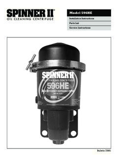
Transcription of Model 996 and Mining - Spinner II
1 ConstructionModel 996and MiningInstallation InstructionsParts ListService InstructionsBulletin 73264 Three connections are required at the centrifuge:1. Oil Inlet (3 UNF Female SAE J514-8 O-ring) Unscrew plastic shipping #8 hose from pointof highest Oil Outlet (3 UNF Female SAE J514-8 O-ring) Unscrew plastic shipping #8 hose tocrankcase above oil Air Inlet (1 4-in. NPT Female Pipe) Unscrew plasticshipping #4 hose from any convenient pointon air supply to air valve cartridge inlet. Do not removecartridge loss of cartridge seal will damage Route hoses to clear exhaust and all movingparts and fasten securely.
2 Be certain pressure oil supply isto OIL IN port on side of centrifuge and return to crankcaseis from OIL OUT port on bottom. Do not removefull-flowfilters. Use the Spinner II centrifuge onlyas a bypass oilcleaner. Remove any previously installed bypass filtersprior to installation of the Spinner II, and block portswhere InstructionsDirty Oil Supply to Centrifuge Oil InletPressure Tap on Engine Most engines, including thelatest models from Cummins, Caterpillar, DDC and Mack,provide a 3 8-in. or 1 2-in. port to supply an auxiliary using end-of-gallery supply points such as thepressure gauge tap.
3 Note on COV(Cut-Out Valve): Idlecut-out valve prevents oil flow into centrifuge at pressuresless than 19 Oil Outlet Return to CrankcaseReturn Opening in Crankcase Most engines have a 1 2-in. or larger oil return opening provided in thecrankcase wall. If unrestricted, this is an ideal oil outlet line connection Return Problems If there are no availabledrain openings, it may be necessary to drill and tap aninspection plate. Remove the plate before modificationand avoid directing the return flow directly onto movingparts. Request assistance from your distributor.
4 Air SupplyAir for the control mechanism can be taken from anyconvenient place on the vehicle air system where there is a constant supply of air, preferably from the dry 8-in. nylon tubing is sufficient or #4 hose can be used ifpreferred. Air pressure can vary from 2 to 125 psig. Noregulators, valves or control devices are required. TheSpinner II control automatically shuts off the air supplywhen the engine stops. SCFM air consumption isalmost too small to II/996 Net Weight lb ( kg)Mounting LocationInstall Vertically 10 .The frame rail is the preferredlocation for mounting the centrifuge.
5 A Spinner II Part70845 spacer is available to facilitate inside frame railmounting, requiring only two holes in the rail. Checkwith manufacturer before drilling. Bulletin 71294 containsa drilling template. Additionally, a Spinner II Part 71421No-Drill mounting bracket kit is also available. Use this kitwhen installation will not permit drilling of the frame Spinner II centrifuge is a high-speed device and isprovided with noise isolators for operator comfort, whichmust be installed as shown above. Care should be usedto prevent metal-to-metal contact with the frame or body,which might result in unnecessary noise or vibration.
6 Thecover clamp can be rotated to any convenient positionand tightened by hand 996 Installation InstructionsDetailed Information AvailableFor optimum performance of your centrifuge, specificinstallation drawings for almost any diesel engine canbe requested from your Flow gpm Turbine Speed rpm10 20 30 40 50 60 70 80 Pressure psig SAE 30 Oil at 167 F / 75 ( ) To remove bowlDimensions in inches (mm)Oil InOil InOilOutAir (17).63 (16) (50).63 (16).79 (20)3/4-16 UNFSAE J514-8O-ring1 railor ( ) (330) (76) (120) (100) (110) ( ) (173) (139) (178) (216) can be rotated 360 (108) (140)Frame railor bracketMounting hole13/32-in.
7 406 ( )3/8-in. (10 mm) Grade 5bolts and nuts tightento 23 lb-ft ( N-m)Not (60) To remove idle cut-out valve retainerNoise isolator installation3/4-16 UNFSAE J514-8O-ringModel 996 Parts ListItemDescriptionPart numberOnly items shown with part numbers are denotes assemblyCentrifuge, Spinner II/ Model 996 kit, clean bowl (1 each items c, l, n and t) ..73265aCover .. 73191bClamp, cover to base ..71281 Tee bolt and knob clamp .. 71282cSeal-cover, Viton .. 71264 Cover bowl .. 73239kBowl-centrifuge .. 73196lInsert, paper-centrifuge bowl (pkg. of 50) .. 73165nSeal-centrifuge bowl, Viton.
8 73240mBaffle/screen-centrifuge .. 73197uBody-centrifuge turbine .. 73194dCentrifuge turbine assembly ..73193(includes items h, k, l, m, nand u)eHousing assembly ..73234 sRepair kit-idle cut-out valve ..71053tSeal-idle cut-out valve ..71054gControl mechanism assembly ..71286 Screw, hex head cap-control mechanism .. 70673M10 x 35 mm (available locally) fSeal-control mechanism (Viton) .. 70996 Repair kit-control float , noise, with washers (set of 4) ..71173(3 8-in. grade 5 bolts and nuts not supplied) qCartridge-air valve assembly (includes item r) ..70938(optional assembly for turbo air supply - 72137)rSeal-air valve cartridge, Viton.
9 70966 Service Cycle At unit rebuild or when 9/021. Shut off engine and allow centrifuge turbine assembly (d) to come toa complete Loosen handle on clamp (b), disengage tee bolt and remove cover(a), using coin in gap to separate cover from Partially withdraw centrifuge turbine assembly (d)from the housing (e)and allow oil to drain from nozzles (o)before removing the centrifuge turbine assembly in one hand and loosen knurledbowl nut (h)several turns until the face of the nut projects beyond thebronze bushing face. Carefully separate centrifuge bowl (k)from tur-bine base (u)by striking the face of the nut (h)with the palm of one handwhile holding the bowl in the other.
10 Do not strike the nut or the bushingwith or against a hard surface or damage will removingthe nut and then remove the bowl and baffle/screen (m). 4. Simply replace the dirty centrifuge bowl with a new one orcarefullyremove the dirt cake from the bowl (k)using a wooden spatula orother non-damaging tool. Wipe out bowl with solvent. Note:To savetime in cleaning, an optional die-cut Bristol paper insert (l)is availableas a service part and may be installed to allow the compressed caketo be removed Wash and clean baffle/screen (m)and turbine base (u). Examine theViton seal and replace, if damaged.


